YONGFAN HVAC - Premium Header
Engineered HVAC & Industrial Air Systems
YONGFAN HVACYOFAN HVAC Home
Energy Efficiency – Sustainability | YONGFAN HVAC
Sustainability & System Optimization

Reduce Unnecessary Energy Use Without Compromising Performance

HVAC energy efficiency is not created by a single “efficient product” — it comes from matching components to actual operating requirements and eliminating system-wide parasitic losses.

YONGFAN approaches energy efficiency through practical engineering decisions that improve how fans, filtration, hydronics, heat exchangers, and controls interact with one another.

Filter Resistance Excessive ΔP spikes fan power demand continuously.
Oversized Fans Operating off-peak duty points forces damper throttling.
Zero-Demand Pumps Fixed pumps running at low load waste baseline electricity.
Mismatched Exchangers Fouling & incorrect surface area surge pump head demand.
HVAC engineers inspecting mechanical system performance

System-Integrated Efficiency

Selection against actual duty points, partial-load modulation, and hydraulic balance.

01 / Selection Principle

Energy Efficiency Starts With Correct Duty Sizing

The goal is not simply to choose equipment with the smallest motor or lowest listed power. The equipment must reliably deliver its target capacity under actual working conditions.
Air Metric Required Airflow
Static Loss Required Pressure
Hydronic Required Water Flow
Pump Head Required Head
Thermal Heat-Transfer Cap
Air Quality Cleanliness Target
“How can the required duty be delivered with less unnecessary system loss?”
YONGFAN Selection Methodology
02 / Airside Dynamics

Fan Energy & System Resistance

The fan does not operate in isolation. A fan’s true operating efficiency depends on where it runs on its performance curve, combined with the cumulative resistance of the air path.
Duty-Point Selection

Bigger Is Not Automatically Better

Selecting a fan only by nominal diameter, motor power, or maximum airflow leads to poor operating points. If excessive airflow is controlled by partially closing dampers, the system wastes pressure that the fan has already consumed electricity to create.

Airflow (CFM)
*
Static ΔP
*
Operating Cond.
Ideal Duty Point
Avoid: Larger motor kW · Excessive casing noise · Damper throttling losses.
Air Path Integrity

Do Not Optimize the Fan While Ignoring the Path

The fan must overcome the combined resistance of every single component in the ductwork. Reducing unnecessary pressure loss directly decreases the static pressure the fan needs to generate.

Ductwork & Bends Air Filters Fire/Control Dampers Cooling Coils Acoustic Silencers Air Terminals
✓ Coordinate fan curves and filter loading together at early design stage.
Filtration Energy Cost

Low-Resistance Air Filtration: Efficiency + Airflow + Resistance

Air filters do not consume electricity directly, but they create constant pressure resistance. YONGFAN ZF9 series utilizes optimized pleat geometry and advanced synthetic media to minimize pressure drop across its operating life.

STAGE 01 Primary Pre-Filter

G1–G4 coarse dust capture with high dust-holding capacity to relieve downstream load.

STAGE 02 F9 Medium Stage

Protects terminal HEPA units, preventing fine particulate loading and extending high-efficiency filter lifespan.

STAGE 03 Terminal HEPA/ULPA

Low-resistance cleanroom media ensuring ISO cleanliness standards without excessive static penalty.
03 / Hydronic & Thermal

Variable Water Supply & Heat Exchanger Optimization

Hydronic energy efficiency is driven by demand-responsive pump staging and correct heat exchange architecture. Physical water treatment protects heat transfer surfaces from performance degradation over time.
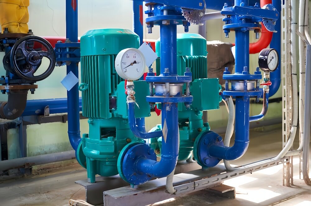
Hydronic plant room with plate heat exchangers and pumps
JFHB Intelligent Variable-Frequency Water Supply PLC pressure feedback · Buffer-tank zero-demand shutdown · Automatic staging
01
Variable-Frequency Operation (VFD)

Water demand fluctuates continuously throughout the day. VFD control smoothly modulates pump speed to real-time flow conditions instead of operating fixed-speed at partial load.

02
Zero-Demand Pump Shutdown

The JFHB buffer-tank architecture stores residual pressure, allowing the main pumps to shut down entirely during zero or low night-time demand, restarting automatically when demand resumes.

03
Physical Scale Prevention (JFGP)

Fouling reduces thermal conductivity. JFGP electronic water treatment conditions chilled/hot water loops without chemicals, preventing scale build-up on heat exchanger plates and pipes.

Transfer Heat With the Right Architecture (Avoid Oversizing)

More surface area is not always better. Sizing against heat load, approach temperature, and water quality prevents excessive water-side volume and pumping losses.

Compact Thermal

Plate Heat Exchangers

High turbulent heat transfer coefficient, compact footprint, and easy maintenance access.

Heavy Duty

Tube Heat Exchangers

Robust shell & tube construction for high pressure, steam duties, or demanding fluid chemistry.

Peak Buffering

Storage Exchangers

Combines instantaneous heat transfer with thermal buffer capacity for peak hot-water demands.

Integrated Skid

Packaged HE Units

Factory-assembled skids complete with primary/secondary pumps, valves, and PLC controls.

04 / Zone Control & Industrial Duty

Demand-Based VAV & Harsh Process Ventilation

Airflow should only be delivered where and when it is needed. Variable-air-volume terminals and specialized process fan architectures avoid continuous full-load waste.
Air Distribution

Coordinated VAV & Central Fan Control

Not every zone requires peak design airflow continuously. VAV terminals adjust supply volume according to zone occupancy and thermal load in offices, hotels, and hospitals.

Control Principle: When VAV terminals modulate down, central fan static pressure setpoints must reset accordingly — otherwise, energy is wasted generating pressure only to throttle it at zone dampers.
Harsh Process & Infrastructure

Reliability Is Part of Lifecycle Efficiency

Industrial ventilation must handle heat, dust, solvent vapors, or corrosive fumes. Fans with motors placed outside the airstream (bifurcated fans) ensure long-term mechanical reliability without rapid efficiency drop.

Tunnel SDS Thrust Sizing: Sized around actual aerodynamic thrust requirement, traffic volume, and fire strategy — avoiding “more fans” as an inefficient default fallback.
05 / Measurement & Retrofits

Measure Before You Change: Data-Driven Upgrades

Energy improvements do not always require replacing complete plants. Targeted component retrofits based on actual measured field data yield the highest ROI without operational disruptions.
Airside Data

Airflow & Pressure

  • Actual operating airflow (CFM/CMH)
  • Static pressure across duct segments
  • Filter differential pressure (ΔP)
  • Fan motor operating current & RPM
Waterside Data

Hydronics & Pumps

  • Flow rate & pump differential head
  • Supply and return water temperatures
  • VFD frequency distribution over 24h
  • System static pressure stability
Thermal Data

Heat Transfer Loops

  • Primary & secondary fluid temps
  • Approach temperature across PHE
  • Scaling and fouling resistance status
  • Valve position vs actual flow balance
06 / Portfolio Contribution

Energy Efficiency by Product Family

Every YONGFAN product family contributes concrete, verifiable efficiency improvements to the overall HVAC engineering package.
01 / AIR QUALITY

Air Filtration Systems

  • Lower initial and operating pressure drop.
  • Correct multi-stage filter dust allocation.
  • Monitoring-based replacement at final ΔP.
02 / AIR MOVEMENT

Ventilation Fans

  • Duty-point selection on optimum efficiency curves.
  • Eliminating oversized motor and casing selections.
  • Matching fan architecture to true system resistance.
03 / DISTRIBUTION

VAV & Air Distribution

  • Demand-based zone airflow modulation.
  • Reduced unnecessary 100% volume operation.
  • Aerodynamic low-leakage damper construction.
04 / THERMAL

Heat Exchange Equipment

  • Optimized plate geometry for low pump head.
  • Proper surface sizing preventing excessive water volume.
  • Packaged skid systems with factory-integrated controls.
05 / WATER SIDE

Hydronic Plant Equipment

  • VFD constant-pressure intelligent regulation.
  • Buffer-tank architecture for zero-demand shutdown.
  • Staged pumping matched to real building demand.
06 / WATER QUALITY

Water Treatment Systems

  • Physical electronic scale prevention (JFGP).
  • Preserving 100% heat-transfer surface efficiency.
  • Reducing pumping losses caused by scaled piping.
07 / Evaluation Framework

Compare Lifecycle Operating Conditions, Not Single Metrics

YONGFAN avoids blanket claims like “saves 30% energy universally”. Real savings depend on load profiles, climate, and control logic. We evaluate systems through a rigorous 6-pillar lifecycle method.
01 / DUTY

Required Duty

Does the equipment reliably satisfy target CFM, head, and heat capacity?

02 / CURVE

Operating Point

Where does the equipment run on its efficiency curve under standard conditions?

03 / LOSSES

System Resistance

How much static pressure or hydraulic friction does the component add?

04 / CONTROL

Load Response

Can the equipment modulate output smoothly under partial-load hours?

05 / AGING

Maintenance

Will fouling, dust loading, or scaling degrade performance prematurely?

06 / TCO

Lifecycle Life

How long will the component maintain its rated efficiency before replacement?

08 / Engineering Handoff

Improve the Efficiency of Your HVAC System

Send us your available operating data and design schedules. Our application engineers will help identify which component-level changes will yield the most impactful, reliable energy savings for your project.


Airflow (CFM/CMH) Static Pressure (Pa) Pump Flow & Head Filter Pressure Drop (ΔP) Water Temperatures Heat Load (kW) Daily Operating Hours Existing Equipment Model
Engineers reviewing energy efficiency data sheets
Direct Application Engineering Support
Duty-matched component schedules, CFD/thermal sizing, and retrofit analysis.
