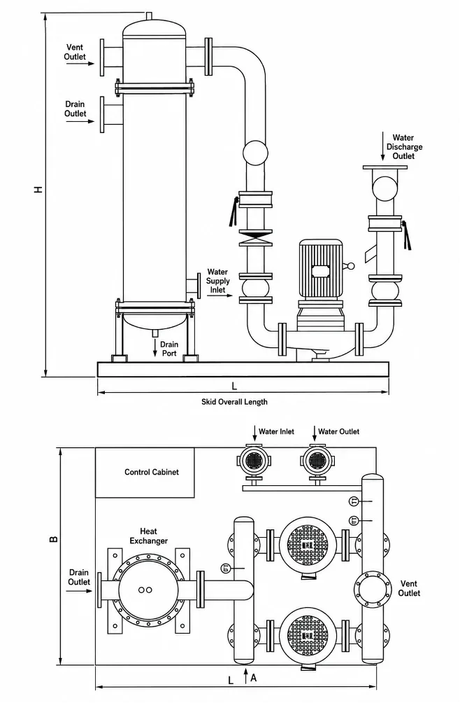
Tube heat exchangers must match duty temperatures, steam pressure, tube material and orientation; a wrong JFSW selection misses flow, fouls early, or complicates plant-room access.
YONGFAN JFSW uses double-thread copper or stainless tubes that induce boundary-layer turbulence on both inside and outside tube walls, delivering high convective transfer across heating (70→95 °C), A/C (50→60 °C), and domestic hot water (5→60 °C) duties.
Ordering a “5.6 MW exchanger” without specifying whether the secondary water rise is 10 K, 25 K, or 55 K results in a 5.5× water flow error.
Copper tubes provide superior conductivity for clean water, but harder or mildly corrosive water requires stainless steel to prevent tube pitting.
Choosing vertical vs horizontal orientation after piping is frozen creates headroom conflicts or blocks tube-bundle extraction clearances.
A JFSW-400 shell appears at multiple capacity points. Sizing must be performed using the complete model code including transfer area.
| Capacity (MW) | Area in Model Code (m²) | Steam Consumption (t/h) | Water Output (t/h) |
|---|---|---|---|
| 0.35 MW | 3.0 | 0.50 | 12 |
| 0.53 MW | 4.8 | 0.80 | 18 |
| 0.70 MW | 5.8 | 1.05 | 24 |
| 1.05 MW | 8.6 | 1.50 | 36 |
| 1.40 MW | 11.5 | 2.10 | 48 |
| 1.75 MW | 14.5 | 2.60 | 60 |
| 2.10 MW | 17.2 | 3.10 | 72 |
| 2.80 MW | 20.5 | 4.15 | 96 |
| 3.15 MW | 23.5 | 4.73 | 108 |
| 3.50 MW | 25.8 | 5.10 | 120 |
| 4.20 MW | 34.4 | 6.30 | 144 |
| 5.00 MW | 40.5 | 7.30 | 172 |
| 5.60 MW | 45.8 | 8.40 | 192 |
| Capacity (MW) | Steam Consumption (t/h) | A/C Water Output (t/h) |
|---|---|---|
| 0.35 MW | 0.50 | 30 |
| 0.53 MW | 0.80 | 45 |
| 0.70 MW | 1.05 | 60 |
| 1.05 MW | 1.50 | 90 |
| 1.40 MW | 2.10 | 120 |
| 2.10 MW | 3.10 | 180 |
| 2.80 MW | 4.15 | 240 |
| 3.15 MW | 4.73 | 270 |
| 3.50 MW | 5.10 | 300 |
| 4.20 MW | 6.30 | 360 |
| 5.00 MW | 7.30 | 430 |
| 5.60 MW | 8.40 | 480 |
| Capacity (MW) | Steam Consumption (t/h) | DHW Output (t/h) |
|---|---|---|
| 0.35 MW | 0.50 | 5.5 |
| 0.53 MW | 0.80 | 8.2 |
| 0.70 MW | 1.05 | 10.9 |
| 1.05 MW | 1.50 | 16.0 |
| 1.40 MW | 2.10 | 21.8 |
| 1.75 MW | 2.60 | 27.0 |
| 2.10 MW | 3.10 | 32.7 |
| 2.80 MW | 4.15 | 43.0 |
| 3.15 MW | 4.73 | 49.0 |
| 3.50 MW | 5.10 | 54.5 |
| 4.20 MW | 6.30 | 65.5 |
| 5.00 MW | 7.30 | 78.2 |
| 5.60 MW | 8.40 | 87.0 |
| Shell Class | Shell Ø | Steam Port | Condensate | Water In/Out |
|---|---|---|---|---|
| 200 | 219 mm | DN65 | DN40 | DN80 |
| 300 | 325 mm | DN80 | DN40 | DN125 |
| 400 | 426 mm | DN125 | DN50 | DN150 |
| 450 | 480 mm | DN125 | DN50 | DN200 |
| 500 | 530 mm | DN150 | DN50 | DN250 |
| 600 | 630 mm | DN200 | DN65 | DN250 |
| 700 | 720 mm | DN200 | DN65 | DN300 |
Specify Heating (70→95 °C), A/C (50→60 °C), or DHW (5→60 °C).
Steam pressure (MPa) or primary hot-water supply/return temperatures.
Required hot water output (t/h) or total thermal load in MW.
Copper vs stainless tubes; vertical vs horizontal installation.
YONGFAN engineers will calculate heat transfer area, nozzle velocities, and supply dimensioned GA drawings.
Double-thread profiles are machine-rolled to precise pitch and depth before expansion into tubesheets.
Every tube-to-tubesheet joint is leak tested to verify zero cross-contamination between steam and water circuits.
Both steam/primary shell side and secondary tube side undergo 1.25× design pressure hydrostatic verification.
Vertical units are braced upright with export-standard port protection and full serial test records.
The documented JFSW family covers 0.35 to 5.6 MW per unit across shell classes 200 through 700.
Because the water temperature rise changes: 192 t/h for 70→95 °C heating (25 K rise), 480 t/h for 50→60 °C A/C (10 K rise), and 87 t/h for 5→60 °C DHW (55 K rise).
N identifies Heating or Air Conditioning duty. R identifies Domestic Hot Water duty in the supplier’s model code.
Use copper for clean water where high thermal conductivity is desired. Select stainless steel for harder, treated, or mildly corrosive water.
Yes. Both orientations are documented. Select based on available mechanical room headroom, floor space, and tube pull clearances.
Yes. The series supports both steam-to-water and water-to-water duties. Water-to-water duties are calculated project-specifically.
JFSW is instantaneous. If domestic hot water demand has sharp peaks, compare with Storage Heat Exchangers.
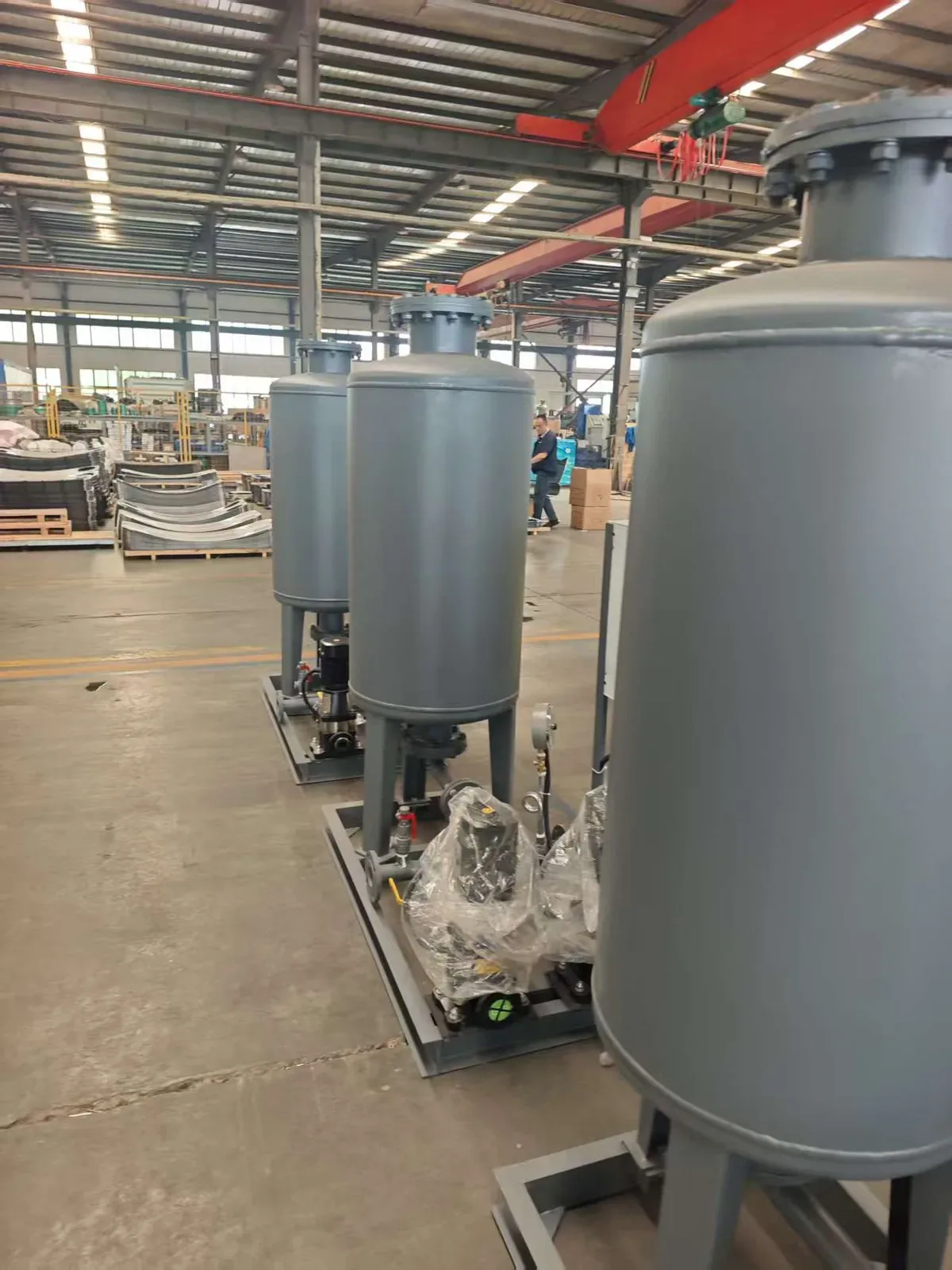
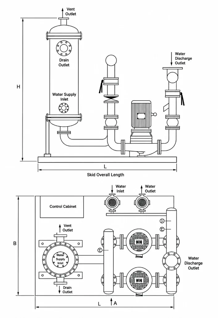
JFSW does not include pumps or controls. For pre-piped pump and control skids, see Packaged Units (ZS/ZW).
Catalog ratings use 0.2 MPa steam. If site steam is 0.4 or 0.6 MPa, recalculate capacity and driving LMTD.
When plant-room footprint is severely restricted and water is clean, review Plate Heat Exchangers.
Send your duty type, primary steam pressure or hot-water temperatures, secondary water flow, water analysis, and orientation preference. YONGFAN engineers will provide exact model selections and GA drawings.