YONGFAN HVAC - Premium Header
Engineered HVAC & Industrial Air Systems
YONGFAN HVACYOFAN HVAC Home
Data Centers & Control Rooms HVAC | YONGFAN
Mission-Critical Electronics Protection

Data Centers & Control Rooms: Particulate & Gas-Phase Corrosion Control

Dust, corrosive gases and unstable airflow can damage electronics long before cooling capacity is exhausted, increasing maintenance risk and shortening equipment service intervals.

Compare YONGFAN staged particulate filtration (ZF7/8), positive-pressure fresh air chemical scrubbers (PSA / PSA-PG), localized server room purifiers (DBS), dedicated in-room recirculation (CA), and water-side hydronic balancing.

Air Quality Target ISA 71.04 Class G1
Fresh Air Range 850 to 68,000 m³/h
Casing Rating 2,000 Pa · <1% Leakage
Hydronic Scope PHE Separation · JFWP
Data center server room aisle with precision cooling and clean airflow systems
Electronic Environment Defense ISA 71.04 Class G1 Gas Removal, Controlled Positive Pressure & ASHRAE TC 9.9 Envelopes
01 / Failure Mechanisms

Electronic Rooms Can Fail While Temperature Looks Normal

A server room holds its thermal setpoint and CRAH units show zero alarms, yet six months later, exposed copper contacts and connector surfaces corrode due to unaddressed chemical contamination.
Server motherboard and microchip contacts corroded by ambient reactive gases
Critical Contamination Risk

Why Thermal Control Does Not Stop Corrosion

Per ASHRAE TC 9.9 Datacom guidance and ANSI/ISA-71.04, gaseous molecular corrosion requires chemisorption filtration rather than refrigeration capacity.

Gaseous Infiltration via Fresh Air

Adding recirculation purifiers without treating incoming make-up air allows H2S and SO2 from industrial surroundings to infiltrate every time doors open.

Impact: Continuous creep corrosion on server PCBs

Fan Pressure Head Starvation

Upgrading to higher particulate grades without checking fan static curves chokes supply airflow as filters load, starving high-density server racks.

Impact: Thermal hotspots & server throttling

Uncontrolled Room Overpressurization

Fresh-air blowers oversized to prevent infiltration without coordinated relief make doors hard to open, blowing air out through unsealed cable penetrations.

Impact: Door operation hazard & energy waste

Idle Intake Backdraft Inflow

When chemical filtration units shut down for servicing, ordinary dampers leak raw contaminated outdoor air directly into the white space.

Impact: Chemical spikes during maintenance

The Protection Strategy Separates Five Operating Variables

Protecting data halls and control rooms requires harmonizing fresh air, recirculation, room pressure, and hydronic stability.

01 Particulate vs. Molecular Gas Chemistry
02 Positive-Pressure Make-Up vs. Recirculation
03 Motorized Airtight Intake Isolation
04 Copper/Silver Reactivity Verification
02 / Equipment Lineup

Engineered Equipment for Data Halls & Control Rooms

Coordinated product families for particulate interception, make-up air chemical scrubbing, room polishing, airtight isolation, and chilled-water loop control.
Architecture 01 · PSA / PSA-PG Series Treated Fresh Air · ISA 71.04 G1

PSA & PSA-PG Chemical Filtration Units (Treated Fresh Air)

The primary defense against ambient corrosive gases. PSA (850–34,000 m³/h) and PSA-PG (1,700–68,000 m³/h) deliver purified, positive-pressure make-up air to keep surrounding industrial contaminants from infiltrating the protected room.

Documented train: G4 particulate pre-filter → two-stage chemical media bed (PCB / CPB chemisorption) → F8 particulate final filter. Double-skin casing rated for 2,000 Pa with <1% leakage at 1,000 Pa. Interlocks with motorized airtight intake dampers and transmits run/alarm signals to BMS/DCS.

Capacity Scope
PSA: 850–34k m³/h · PSA-PG: 1.7k–68k m³/h
Filtration Stages
G4 Pre + 2-Stage Chemisorption + F8 Final
Output Standard
ISA S71.04-2013 Class G1 Severe Corrosive Control
Media Life Benchmark
Up to 2 years under documented typical loads
Capacity Sizing Rule: Select between PSA and PSA-PG based on required outdoor fresh-air rate, room envelope leakage, and plant redundancy strategy.
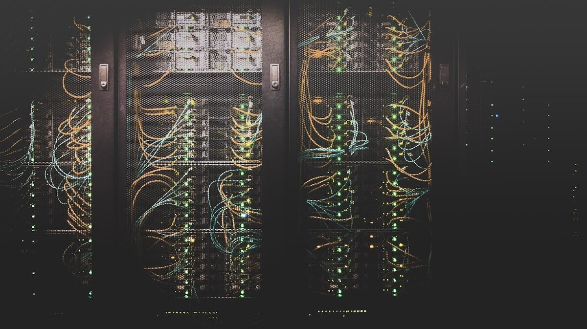
PSA fresh air chemical filtration unit protecting central control room
PSA-PG High-Volume Make-Up Air Unit
Key Features:
  • Motorized airtight intake isolation damper
  • DCS/PLC Modbus status & alarm relay
  • Gas detector interlock & VFD speed control
  • Optional online copper/silver corrosion monitors
Architecture 02 · CA & DBS Series Indoor Recirculation · <65 dB(A) Quiet

CA & DBS Indoor Chemical Recirculation Purifiers

Controls residual chemical contaminants already present inside the room from door traffic, internal materials, or minor infiltration. CA is a dedicated standalone indoor purifier; DBS supports dual-mode positive-pressure supply or recirculation.

The CA Series covers 850 to 6,800 m³/h across four vertical configurations (500V, 1000V, 2000V, 4000V). Built-in VFD, LCD display, sound-attenuated fan rated <65 dB(A), and pre-filled rail-mounted MediaPAK PK-12 modules for clean, tool-free media servicing without loose carbon dust.

CA Airflow Models
500V (850), 1000V (1.7k), 2000V (3.4k), 4000V (6.8k m³/h)
Acoustic Rating
<65 dB(A) sound-treated internal casing
Media Modules
Pre-filled MediaPAK PK-12 (PCB / CPB chemistry)
DBS Versatility
Dual-mode: Positive pressure or Recirculation (~249 Pa ESP)
Recirculation Boundary: CA does not introduce outdoor make-up air or generate positive room pressure. Pair CA with PSA when both room pressurization and internal polishing are required.
CA vertical indoor recirculation chemical filtration unit in telecom server room
CA-2000V Vertical In-Room Chemical Purifier
CA Standard Vertical Ratings:
  • 500V: 850 m³/h · 0.75 kW · 25 Pa ESP
  • 1000V: 1,700 m³/h · 1.5 kW · 25 Pa ESP
  • 2000V: 3,400 m³/h · 2.2 kW · 25 Pa ESP
  • 4000V: 6,800 m³/h · 4.0 kW · 25 Pa ESP
Architecture 03 · ZF7(8) / ZZH / ZDZ Low ΔP · ISO 16890 / EN 779

Staged Particulate Filtration for Data Halls

Data centers recirculate massive air volumes. Particulate filtration must deliver high dust-holding capacity without consuming excessive fan static pressure head.

YONGFAN’s ZF7(8) synthetic bag filter family provides F7 (96 Pa initial ΔP) and F8 (100 Pa initial ΔP) grades at 600 mm depth, rated from 1,300 to 3,200 m³/h. ZZH V-bank filters provide high-airflow compact capacity up to 3,600 m³/h, while ZDZ mini-pleat panels fit shallow AHU filter sections.

Bag Grades
ZF7 (F7 · 96 Pa) · ZF8 (F8 · 100 Pa)
Compact V-Bank
ZZH V-Bank format to 3,600 m³/h per cell
Pre-Filter Options
CG panel (25–45 Pa) · CNL washable mesh
HEPA Option
GCDZ (≤160 Pa initial) for clean microelectronics
Fan Head Budgeting: Calculate loaded filter resistance (up to 2.5× initial ΔP) when selecting CRAH fan speeds to avoid airflow degradation over the filter life.
ZF7 synthetic pocket bag filter bank in data center AHU
ZF7(8) Synthetic Pocket Bag Filters
Selection Guidance:
  • ZF5(6) for coarse pre-protection (50–55 Pa)
  • ZF7(8) for fine dust protection of server coils
  • ZZH V-Bank where 600 mm bag length cannot fit
  • Flame-retardant synthetic media per UL 900
Architecture 04 · Hydronics & Controls Loop Separation · PICV Dynamic Balancing

Water-Side Loop Separation & Dynamic Flow Control

Supporting components for chilled-water data center circuits, secondary cooling loops, and plant-room pressure maintenance.

Gasketed Plate Heat Exchangers (4–900 m³/h, 1.0–2.5 MPa) provide hydraulic separation between primary chiller loops and secondary CRAH/in-row circuits. JFWP expansion units (48–480 m³ capacity) maintain system static pressure. Dynamic PICV control valves and balancing valves prevent low delta-T syndrome across terminal cooling coils.

PHE Flow Scope
4 to 900 m³/h · Design pressure to 2.5 MPa
Pressure Control
JFWP Expansion Units · 2.4 to 24 m³/h make-up
Dynamic Valves
Pressure-Independent Control Valves (PICV)
Support VAV
YFVAV-S-T100 (122–6,232 m³/h) for admin/battery zones
Scope Demarcation: YONGFAN supplies loop separation exchangers, hydronic valves, and expansion equipment — primary chillers, CRACs, and CDUs are engineered by the cooling plant contractor.
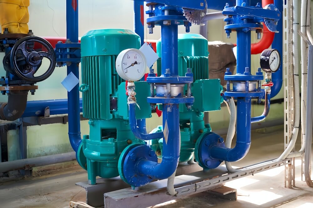
Gasketed plate heat exchanger and balancing valves in data center plant room
Plate Heat Exchanger & Dynamic Balancing Valves
Key Capabilities:
  • Hydraulic loop isolation for free-cooling loops
  • Modbus/BACnet motorized control valves
  • Vacuum degassing and automatic make-up
  • Differential-pressure balancing across server rows
03 / Selection Matrix

Protected-Room Component Routing Table

Cross-reference YONGFAN components by protected-room requirement, supplier boundaries, and the first technical confirmation input.
Protected-Room Requirement First YONGFAN Route Supplier-Supported Boundary First Input to Confirm Specification Action
General particulate control ZF7/F8 (96/100 Pa); Standard models 1,300–3,200 m³/h Particle target + available fan static pressure Configure ZF
Standard treated fresh air 850–34,000 m³/h · ISA 71.04 Class G1 Fresh-air quantity + site gas analysis Configure PSA
High-volume treated fresh air 1,700–68,000 m³/h · 2× PCB chemisorption Fresh-air quantity + redundancy plan Configure PSA-PG
Local positive pressure / recirculation 2,000 Pa casing; <1% leakage; ~249 Pa ESP Operating mode + target gas profile Configure DBS
Dedicated room recirculation 850–6,800 m³/h · 500V to 4000V · <65 dB(A) Room volume + internal gas load Configure CA
Intake isolation Low-leakage Class 4 · Spring-return actuator Duct size + leakage class + actuator voltage Configure Damper
Support-zone airflow regulation Approx. Ø125–Ø400 mm · 122–6,232 m³/h Zone airflow + duct pressure range Configure VAV
Chilled-water loop separation 4–900 m³/h · 1.0 / 1.6 / 2.5 MPa Heat duty + four fluid temperatures Configure PHE
Chilled-water branch balancing Dynamic & static balancing · Modbus DDC Flow rate + differential pressure Configure Valve
04 / Procurement Protocol

Information Required for a Data Center HVAC Quotation

Providing clear room dimensions, make-up airflow rates, target gas concentrations, and pressure strategy ensures exact equipment sizing.
STEP 01

Room & Airflow Parameters

State room dimensions (L×W×H), design outdoor make-up air volume, existing CRAH supply/return rates, and required positive pressure differential (Pa).

STEP 02

Contaminant Analysis

Provide measured chemical gas concentrations (H2S, SO2, Cl2, NOx in ppb), outdoor air source conditions, and ISA 71.04 target class.

STEP 03

System Architecture

Confirm whether the project requires fresh-air make-up treatment (PSA), indoor recirculation (CA), dual-mode (DBS), or combined staging.

STEP 04

Hydronic & Valve Data

Provide chilled-water flow, entering/leaving temperatures, branch differential pressure, valve DN size, and BMS communication protocol.

Engineering Handoff

Required Parameters for Data Center RFQs

Send your available schedule data. YONGFAN application engineers will verify media life, make-up air static head, and valve control authority.

1. Room Volume & Target Pressure (Pa)
2. Outdoor Make-Up Air Volume (m³/h)
3. Gas Species: H₂S, SO₂, Cl₂, NOx, VOCs (ppb)
4. Protection Target: ISA 71.04 Class G1
5. Particulate Filter Grade (ISO 16890 / EN 779)
6. Casing Leakage Standard (<1% @ 1,000 Pa)
7. Chilled-Water Flow & Delta-T Parameters
8. Corrosion Reactivity Coupon Monitoring
05 / Manufacturing Verification

Continuous Facilities Need Maintainable Filtration Hardware

Verified manufacturing controls, double-skin casing pressure testing, tool-free MediaPAK module rails, and automated media batch testing.
MediaPAK PK-12

Pre-Filled Module Rails

CA and DBS units use modular, pre-filled MediaPAK canisters on slide-in guide rails, allowing rapid maintenance without loose carbon spillage.

Casing Integrity

Pressure & Leak Testing

PSA/DBS double-skin casings tested to 2,000 Pa structural integrity with verified leakage below <1% at 1,000 Pa to eliminate raw air bypass.

Acoustic Testing

<65 dB(A) In-Room Fan QA

Every CA internal backward-curved fan assembly is dynamically balanced and acoustically checked to maintain quiet operation in occupied control rooms.

Compliance

UL 900 Flame Retardancy

Chemical media and synthetic particulate filter elements comply with UL 900 flame retardancy standards for critical mission-critical infrastructure.

06 / Engineering Knowledge

Data Centers & Control Rooms Frequently Asked Questions

Technical answers to key selection questions regarding gas-phase chemistry, positive pressurization, CA vs. PSA, and hydronic loop isolation.

Do data centers always need chemical filtration?

No. Chemical filtration is necessary when corrosive molecular gases (H2S, SO2, Cl2, NOx) are present in ambient outdoor air or nearby industrial processes. Particulate filtration and gas-phase filtration solve different contamination mechanisms.

What is the difference between PSA and CA?

PSA treats incoming fresh outdoor air and creates positive room pressure to prevent unconditioned infiltration. CA is an indoor recirculation unit that continuously polishes air already inside the room.

Can CA create positive room pressure?

No. CA operates as a 100% recirculation unit. Positive room pressure requires conditioned, treated make-up air (via PSA or DBS in supply mode) delivered in excess of room exhaust and leakage.

When should PSA-PG be used instead of PSA?

Use PSA-PG where treated fresh-air demand is large. PSA is documented at 850–34,000 m³/h; PSA-PG is documented at 1,700–68,000 m³/h per unit with two-stage PCB chemical media.

What is DBS used for in server rooms?

DBS can be configured for either positive-pressure fresh air supply or in-room recirculation. It features a 2,000 Pa casing, ~249 Pa ESP, local/remote control, and DCS status outputs.

Why monitor copper or silver corrosion if gas filters are installed?

Because the room environment depends on more than the filter media: door openings, cable penetration leakage, and outdoor gas surges can impact electronics. Reactivity coupons verify the actual installed room severity per ISA 71.04.

Does YONGFAN supply the complete precision cooling plant?

YONGFAN supplies air filtration, gas-phase scrubbers, airtight dampers, VAV terminals, plate heat exchangers, and hydronic valves. Chillers, CRAH/CRAC units, and liquid CDUs are supplied by the primary cooling contractor.

Should I use HEPA filtration for every data center?

Not automatically. Select particulate efficiency based on project requirements and available fan pressure. Standard data halls typically utilize M6–F8 filters (ZF7/8), reserving HEPA (GCDZ) for specialized fab/clean spaces.

07 / Application Boundaries

Data-Center Component Scope Stops Before the Cooling Plant

Understanding system boundaries ensures clear engineering responsibility across data center infrastructure projects.
Boundary 01 / Primary Cooling

Not CRAC / CRAH / CDU Units

YONGFAN does not manufacture primary CRAC/CRAH precision air conditioners, chiller chillers, or direct-to-chip liquid cooling CDUs.

Boundary 02 / PUE / Tier Rating

Facility Design Responsibility

Facility PUE metrics, Uptime Institute Tier ratings, and redundancy classifications remain the responsibility of the lead MEP design consultant.

Boundary 03 / Rack Air Containment

Not Rack-Level Containment

YFVAV-S-T100 terminals serve ducted support spaces; rack hot/cold aisle containment systems belong to white space fitout scope.

Boundary 04 / Media Saturation

Routine Life Monitoring

Chemical media must be monitored for gas breakthrough over time; differential pressure alone does not indicate gas-phase chemical saturation.

08 / Engineering Handoff

Plan Data Center & Control Room HVAC Components

Send your room volume, make-up airflow rate, measured gas analysis, and hydronic parameters — YONGFAN engineers will size compliant chemical filtration and airside packages.

Make-Up Air Flow (m³/h) ISA 71.04 Class G1 Target H₂S · SO₂ · Cl₂ · NOx (ppb) CA In-Room Recirculation Casing <1% Leakage @ 1,000 Pa Chilled-Water PHE Sizing
Engineers reviewing data center air filtration and control room schedules
Data Center Application Engineering
ISA 71.04 compliance verification, media life calculations & hydronic balancing support.