
YONGFAN HVAC - Premium Header
Engineered HVAC & Industrial Air Systems
YONGFAN HVACYOFAN HVAC Home
Heat Recovery & Energy Optimization | YONGFAN
Thermal Engineering & Hydronic Recovery

Heat Recovery & Energy Optimization: Thermal Architecture & System Sizing

Heat recovery is useful when one part of a building or industrial process has usable thermal energy while another part needs heating or domestic hot water.

The engineering task is to transfer or retain that energy without creating excessive pumping, fouling, control or maintenance penalties. Discover YONGFAN gasketed plate exchangers (down to ~1 °C approach), packaged heating skids (0.21–21 MW), JFSW turbulent tubes (0.35–5.6 MW), U-tube storage (10 kW–10 MW), and JFLN condensate recovery.

Plate Flow 4 to 900 m³/h (DN15–250)
Packaged Skids 0.21 to 21 MW per unit
Approach ΔT Down to ~1 °C capability
Storage Range 100 to 15,000 L vessels
Industrial plate heat exchanger and hydronic pump station in district heating plant
Hydronic & Thermal Balance Available Heat → Receiving Load → Exchanger Area → Pumping Penalty → Controls
01 / Engineering Methodology

Recover Useful Heat Before Adding New Heat

A heat-recovery project must start with the source, not the heat exchanger. Define the source fluid, terminal temperatures, flow rate, schedule coincidence, and fouling risk.
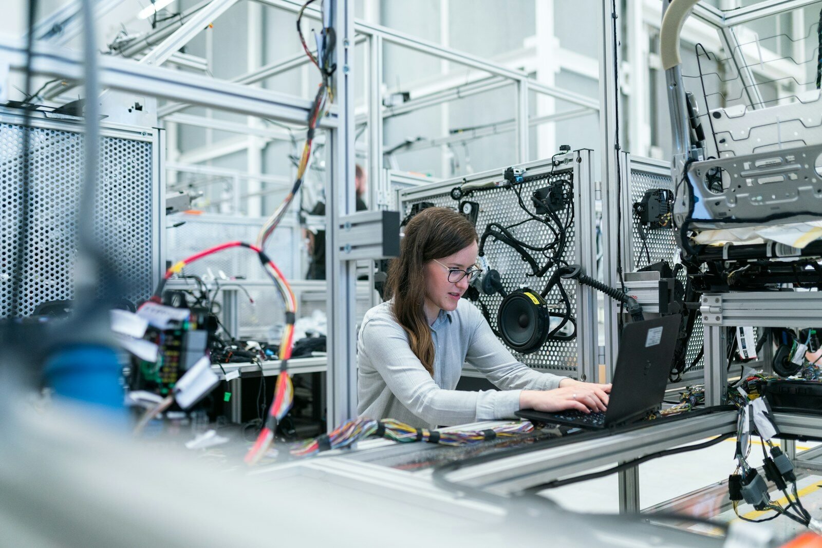
Engineers inspecting industrial heat exchange headers and secondary hydronic loops
The Four Terminal Temperatures

Thermal Driving Force Defines Feasibility

Hot Inlet → Hot Outlet vs Cold Inlet → Cold Outlet. A large warm flow has zero recovery value if the receiving load is absent when heat is available.

Heat Recovered vs Energy Saved

Transferring kW is not the same as saving money. Actual reduction depends on what energy is displaced (boiler fuel, steam, grid electricity, or make-up heat).

Key Rule: Calculate against displaced baseline fuel

Approach Temperature Trade-Off

YONGFAN plate exchangers achieve down to ~1 °C approach, but forcing an ultra-tight approach multiplies plate area, footprint, and hydraulic resistance.

Key Rule: Optimize approach vs plate capital & pumping

Pumping Power Penalty

Corrugated plates create turbulence to enhance transfer, but high channel velocity consumes fan/pump head. High pumping can erase thermal energy savings.

Key Rule: Net Benefit = Thermal Recovered − Pumping kW

Temperature Program ΔT Impact

Lower ΔT means much higher water flow for identical MW duty. For a 2.1 MW load, 60/85 °C requires 72 t/h, whereas 45/55 °C requires 181 t/h.

Key Rule: ΔT governs pipe size, valves & skid footprint
The Complete Heat Recovery Optimization Sequence
Available Heat → Receiving Load → Temperature Match → Exchanger Area → Pressure Drop → Pumping → Controls → Metering

Never specify the smallest possible exchanger or tightest approach in isolation. The most efficient design maximizes net delivered energy while keeping water-side pressure loss within available pump head budgets.

02 / Equipment Architectures

YONGFAN Heat Recovery & Thermal Exchange Portfolio

From compact gasketed plate exchangers to packaged modular skids, turbulent tube units, thermal storage vessels, and steam condensate return.
Architecture 01 · Gasketed Plate HX Liquid-to-Liquid · Up to 900 m³/h · 500 m²

Gasketed Plate Heat Exchangers: High Thermal Intensity & Close Approach

The primary family for indirect liquid-to-liquid heat recovery. True counter-flow channel architecture achieves high heat transfer coefficients and allows minimum approach temperatures down to approximately 1 °C.

Operating Envelope: Unit flow rates from 4 to 900 m³/h, total assembled heat-transfer area from 0.2 to 500 m², plate unit areas from 0.02 to 1.3 m², port diameters from DN15 to DN250. Design pressure classes of 1.0, 1.6, and 2.5 MPa, with design temperatures up to 170 °C (long-term recommended ≤150 °C).

Capacity Range
4 – 900 m³/h · 0.2 – 500 m² area
Pressure & Temp
1.0 / 1.6 / 2.5 MPa · Design to 170 °C (≤150 °C cont.)
Plate Metallurgy
SUS304, 316, 316L, 316Ti, 321, Titanium TA1, Hastelloy, RS-2
Fouling Options
Wide-gap BRb0.5 / BRb0.7 / BRb0.9 for fibrous/viscous fluids
Pressure Drop Budget: District heating primary and building secondary loops operate on different pump head budgets. Specify allowable ΔP for both circuits separately.
Stainless steel gasketed plate heat exchanger installed with flanged connections
Gasketed Plate Heat Exchanger
Best Suited For:
  • District heating / secondary loop isolation
  • Process water heat recovery (clean streams)
  • Heat pump circuit hydraulic separation
  • Applications where plate count may expand later
Architecture 02 · Packaged Units Integrated Skid · 0.21 to 21 MW per Unit

Packaged Plate Heat Exchange Units: Coordinated Thermal Stations

A bare exchanger transfers heat; a packaged station coordinates the entire hydronic sub-plant. Integrates plate heat exchanger, primary/secondary circulation pumps, automated make-up system, modulating control valves, temperature/pressure transmitters, safety relief, and intelligent PLC control cabinet onto a unified structural base.

Thermal Range: Covers 0.21 to 21 MW per skid. Supports steam-to-water (saturated steam ≤0.4 MPa) and water-to-water (95/70 °C primary). Documented secondary programs include 60/85 °C radiator heating (ΔT=25K) and 45/55 °C floor heating/HVAC (ΔT=10K). Features ZS (VFD make-up) or ZW (expansion vessel make-up).

Capacity Envelope
0.21 – 21 MW per factory skid
Hydronic Integration
Pumps, valves, PLC cabinet, instruments & make-up on one frame
Make-Up Types
ZS (Variable Frequency Drive) · ZW (Expansion Vessel)
Secondary ΔT Impact
Radiator: 25K ΔT (72 t/h @ 2.1MW) · Floor: 10K ΔT (181 t/h @ 2.1MW)
Temperature Program Verification: Never size pumps or skid piping without confirming the secondary ΔT; lower ΔT requires 2.5× the water flow.
Packaged plate heat exchange skid with dual circulating pumps and control cabinet
Packaged Plate Heat Exchange Station
Best Suited For:
  • Commercial building central heating substations
  • District heating consumer substations
  • Fast-track mechanical plant rooms (plug-and-play)
  • Variable-load HVAC and floor heating systems
Architecture 03 · JFSW Series Enhanced Shell & Tube · 0.35 to 5.6 MW

JFSW Double-Thread Turbulent Heat Exchangers: Enhanced Tube Transfer

Enhanced shell-and-tube unit utilizing double-threaded spiral copper or stainless-steel tubes to induce boundary-layer vortex turbulence. Increases the overall heat transfer coefficient compared to plain tube exchangers while maintaining a wider, more open flow passage.

Thermal Range: 0.35 to 5.6 MW per unit. Available in vertical or horizontal orientations for steam-water (0.2 MPa saturated steam) and water-water service. Documented programs: Heating 70 → 95 °C, Air Conditioning 50 → 60 °C, Domestic Hot Water 5 → 60 °C.

Capacity Range
0.35 – 5.6 MW per unit
Operating Media
Steam-Water (0.2 MPa steam) · Water-Water
Tube Metallurgy
Double-thread spiral copper or stainless steel
Orientation
Vertical (compact footprint) or Horizontal arrangements
Fouling Note: While threaded geometry disturbs boundary-layer scale formation, it does not replace water-side filtration or routine descaling procedures.
Industrial tubular heat exchanger shell and tube bundle during assembly
JFSW Double-Thread Enhanced Tube Exchanger
Best Suited For:
  • Steam-to-water heat exchange without sub-cooling risks
  • Water circuits with moderate suspended solids
  • Industrial plant hot water production
  • Vertical plant rooms with restricted floor area
Architecture 04 · Storage & Condensate U-Tube · Floating Coil · JFLN

Thermal Storage & Steam Condensate Recovery

Energy optimization often involves buffering intermittent peaks or recovering hot water that crosses system boundaries.

U-Tube Storage Exchangers: 100 to 15,000 L vessel storage, 10 kW to 10 MW thermal capacity, with withdrawable tube bundle for full descaling.
Floating Coil Storage Exchangers: 100 to 15,000 L, 21–1,045 kW steam / 10–523 kW water, engineered for heat pump, solar, and boiler recovery.
JFLN Condensate Recovery: Closed-loop recovery of hot steam condensate (80–150 °C standard, up to 180 °C upgraded) to eliminate flash steam waste and save treated boiler feedwater.

Storage Volumes
100 – 15,000 L (U-Tube & Floating Coil)
Low-Temp Sources
Floating coil sized for heat pumps, solar thermal & boilers
JFLN Condensate
JFLN-1 to JFLN-100 (t/h) · Anti-cavitation pumping
Serviceability
Withdrawable U-tube bundle · Detachable floating coil joints
Storage Losses: Larger vessels have standing thermal radiation losses. Balance peak storage volume against recovery time and thermal insulation thickness.
Pressure storage vessel and steam condensate return pump station in central boiler room
Thermal Storage & JFLN Condensate Skid
Key Design Considerations:
  • Reserve axial clearance for U-tube bundle withdrawal
  • Calculate floating coil area at true heat pump supply temp
  • Preserve condensate temperature without flashing cavitation
  • Verify return condensate quality before boiler entry
03 / Selection Matrix

Heat Recovery Technology Routing Table

Match your available waste heat source and process load directly to the recommended YONGFAN equipment architecture.
Project Condition Primary YONGFAN Route Documented Range / Sizing Main Optimization Decision Action
Liquid-to-Liquid Indirect Recovery
Continuous Flow
Gasketed Plate Heat Exchanger 4–900 m³/h · 0.2–500 m² · DN15–DN250 · to 170 °C Approach temperature (~1 °C) vs. allowable pressure drop Configure Plate
Complete Substation Skid
Heating / DHW / HVAC
Packaged Plate Heat Exchange Unit 0.21–21 MW per unit · ZS (VFD) or ZW (Expansion) make-up Coordinate exchanger, pumps, controls, and make-up as one system Configure Skid
Steam-Water or Open Tube Duty
Turbulent Flow
JFSW Double-Thread Exchanger 0.35–5.6 MW · 0.2 MPa steam · Spiral copper/SS tubes Temperature program, fouling management, and vertical space fit Configure JFSW
Short-Duration Peaked Hot Water
Buffer Storage
U-Tube Storage Heat Exchanger 100–15,000 L storage · 10 kW–10 MW · to 2.5 MPa Storage volume vs. recovery interval; withdrawable tube bundle space Configure U-Tube
Variable / Low-Temp Heat Source
Heat Pump · Solar
Floating Coil Storage Exchanger 100–15,000 L · 10–523 kW water / 21–1,045 kW steam Coil heat-transfer area at true source temp; dynamic scale cracking Configure Floating
Steam Condensate Available
Water & Heat Return
JFLN Condensate Recovery Unit JFLN-1 to JFLN-100 (t/h) · 80–150 °C (180 °C upgraded) Preserve hot condensate without cavitation; save treated water & reheat Configure JFLN
Fouling-Prone / Viscous Fluids
Heavy Duty
Wide-Gap Plate / Enhanced Tube BRb0.5 / BRb0.7 / BRb0.9 wide gap · JFSW threaded tubes Maintain thermal & hydraulic performance over time under real fluid loading Configure Wide-Gap
04 / Engineering Protocol

Information Required for a Heat Recovery Review

Submit these 12 engineering parameters to size thermal transfer surfaces, calculate hydraulic pressure loss, and optimize control sequences.
STEP 01

Thermal Temperatures & Flow

State hot-side inlet/outlet and cold-side inlet/outlet temperatures (°C) and design flow rates (m³/h or t/h).

STEP 02

Hydraulic Pressure Budgets

Specify maximum allowable pressure drop (ΔP in kPa) for both primary and secondary circuits separately.

STEP 03

Fluid Chemistry & Fouling

Provide fluid composition, pH, chlorides (mg/L), suspended solids, viscosity, and chemical compatibility requirements.

STEP 04

Controls & Storage Profile

State operating schedule coincidence, peak draw duration, storage volume requirement, and PLC communication protocols.

Engineering Handoff

12-Point Heat Recovery RFQ Checklist

Send your thermal parameters and process schematics. YONGFAN application engineers will issue thermal heat-transfer calculations, pressure drop curves, and skid dimensional drawings.

1. Heat Source Fluid & In/Out Temperatures (°C)
2. Receiving Load Fluid & In/Out Temperatures (°C)
3. Design Heat Load (kW / MW) & Mass Flow (m³/h)
4. Allowable ΔP for Hot & Cold Circuits (kPa)
5. Design Operating Pressure & Class (MPa)
6. Plate / Tube Metallurgy (304, 316L, Ti, Cu)
7. Operating Hours & Schedule Coincidence
8. Peak Draw Volume & Storage Capacity (L)
9. Condensate Steam Pressure & Lift Head (JFLN)
10. Water Chemistry, Chlorides & Solids Content
11. Physical Plant Room Clearances (Axial space)
12. Make-Up Type (ZS Inverter vs ZW Expansion)
05 / Manufacturing Verification

Exchanger Quality & Thermal Testing Standards

Hydrostatic pressure testing at 1.25× design pressure, dye penetrant weld inspection, and automated skid performance validation.
Hydrostatic QA

1.25× Pressure Shell Test

Every plate pack, shell, and storage vessel undergoes hydrostatic proof testing at 1.25× design rating under GB 150 / GB 151 standards.

Weld Integrity

NDT & Dye Penetrant Check

Non-destructive radiographic and liquid penetrant inspection on vessel longitudinal seams, nozzle welds, and tube-to-tubesheet joints.

Skid Testing

Full Run-Testing on Packaged Units

Pre-dispatch factory wet-testing of pumps, VFD inverters, modulating valve response, pressure sensors, and automated make-up sequences.

Gasket Integrity

Channel Seal & Anti-Cross Leak

Double-gasket sealing with external weep leakage grooves prevents cross-contamination between primary and secondary fluid circuits.

06 / Engineering Knowledge

Heat Recovery Frequently Asked Questions

Direct engineering answers regarding plate sizing, approach temperatures, thermal storage, and condensate recovery.

Does the smallest heat exchanger use the least energy?

Not necessarily. A smaller plate pack can force higher fluid velocity, creating high hydraulic resistance that increases continuous pump electrical demand. Sizing must optimize thermal transfer and pumping power together.

Should I always specify the closest possible approach temperature?

No. While YONGFAN plate heat exchangers can achieve down to ~1 °C approach, a tighter approach exponentially increases required transfer area, equipment cost, footprint, and hydraulic pressure drop.

Can a plate heat exchanger recover heat from any fluid?

No. Fluid chemistry, chloride concentration, suspended solids, viscosity, and chemical compatibility dictate whether plate materials (304, 316L, titanium, Hastelloy) and gasket elastomers (NBR, EPDM, Viton) are suitable.

When does thermal storage help energy optimization?

Storage is valuable when hot-water draw is highly peaked or intermittent, allowing smaller boilers or heat pumps to charge the vessel steadily between draw cycles. Vessel standby thermal losses must be factored in.

Can heat pumps use YONGFAN storage heat exchangers?

Yes. YONGFAN positions the Floating Coil storage family for heat pump and solar thermal applications. Coil heat-transfer surface area must be calculated at the actual heat pump supply temperature (e.g. 45–55 °C).

Does JFSW turbulent tube geometry eliminate scaling?

No. Spiral threaded tube geometry generates fluid turbulence that disturbs boundary-layer scale accumulation relative to plain tubes, but proper water softening and periodic maintenance remain essential.

Does YONGFAN guarantee a fixed heat recovery percentage?

No universal percentage applies to all facilities. Net savings depend on terminal temperatures, flow rates, operating hours, system pressure losses, and the specific displaced primary fuel source.

Is condensate recovery part of the same calculation as plate heat recovery?

No. Condensate recovery (JFLN) is a steam-infrastructure solution that recovers both treated boiler feedwater and sensible heat under pressurized, anti-cavitation conditions, requiring independent evaluation.

07 / Application Boundaries

Thermal Engineering Scope and Technical Boundaries

Clear delineation of engineering responsibilities ensures thermal equipment integrates seamlessly with building services.
Boundary 01 / Fluid Verification

Water Chemistry Analysis

YONGFAN selects plate metallurgy based on provided water data; periodic water quality testing and chemical treatment remain with the plant operator.

Boundary 02 / Hydraulics

External Distribution Piping

YONGFAN provides packaged skid headers and pump sizing; external distribution network friction, balancing, and riser losses belong to MEP designers.

Boundary 03 / Electrical

Primary Power Distribution

YONGFAN supplies skid-mounted control panels and VFDs; incoming main electrical feeder lines, breakers, and transformer capacity belong to electrical contractors.

Boundary 04 / Civil & Access

Maintenance Clearances

Plant room layout must preserve frame movable-plate opening zones and axial U-tube bundle pull clearances before piping walls are finalized.

08 / Thermal Consultation

Discuss a Heat Recovery & Energy Strategy

Send your source and load fluid temperatures, design flow rates, and operating schedules — YONGFAN thermal application engineers will model heat-transfer performance, optimize hydraulic pressure drops, and provide detailed equipment proposals.

Gasketed Plate Heat Exchangers Packaged Heating Skids (0.21–21 MW) JFSW Turbulent Tubes (0.35–5.6 MW) U-Tube Storage (100–15,000 L) Floating Coil Storage (Heat Pump/Solar) JFLN Steam Condensate Units
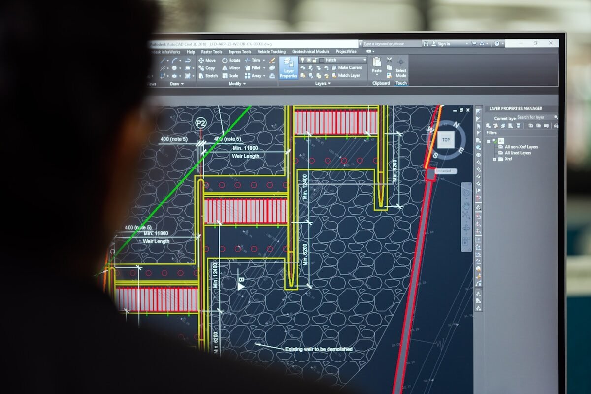
Engineers reviewing industrial heat recovery and hydronic plant drawings
YONGFAN Thermal Engineering Support
Plate calculations, hydraulic pressure optimization & modular packaged skids.