
YONGFAN HVAC - Premium Header
Engineered HVAC & Industrial Air Systems
YONGFAN HVACYOFAN HVAC Home
HVAC Balancing Valves | YONGFAN
Hydronic Balancing · Static & Dynamic · DN15 to DN800 · 20–300 kPa

HVAC Balancing Valves: Matched to Design Flow, ΔP & Duty

Hydronic balancing is not a one-time commissioning detail. The valve architecture determines whether design flow remains stable when branch resistance, terminal load or system differential pressure changes.

Compare YONGFAN manual static balancing valves (DRV, KPF DN15–DN600), dynamic automatic flow balancing valves (BYF, B-Type DN15–DN800), ZYC self-actuated branch differential-pressure controllers, and KYEJ electric static balancing valves with 0–10 V / 4–20 mA remote adjustment.

DRV / KPF Static DN15–DN600 · Lockable
BYF Dynamic Flow DN15–DN250 · 20–300 kPa
B-Type Dynamic DN50–DN800 · ±5% Acc
KYEJ Electric AC 24 V · 0–10 V / 4–20 mA
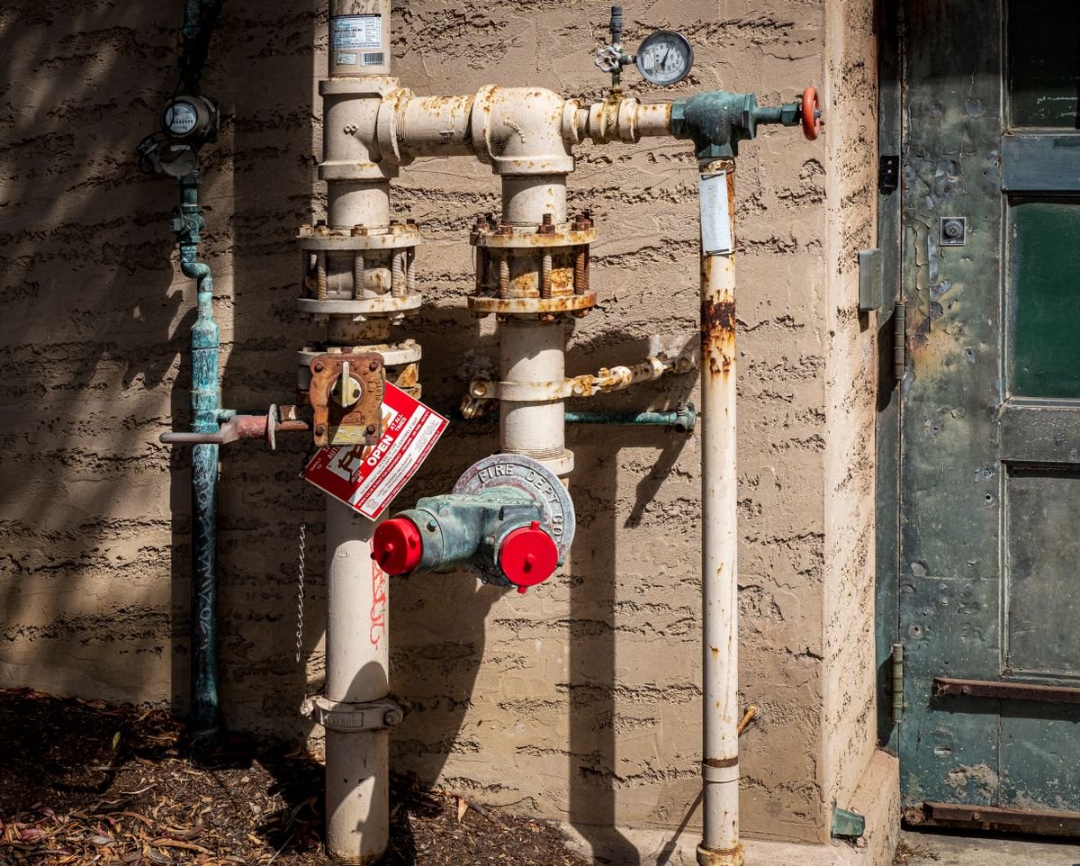
Hydronic balancing valves and pressure measurement ports on commercial HVAC distribution header
Hydronic Flow Distribution Manual Static Commissioning · Dynamic Automatic Cartridge · Branch DP Stabilization
01 / Hydronic Flow Analysis

Hydraulic Imbalance Appears As Unequal Flow, Noise & Pump Head Waste

Near coils overflow while distant index branches starve. Increasing pump speed masks distant starvation while forcing excess differential pressure everywhere else.
Hydronic pipework, test ports, and balancing valves on commercial HVAC riser
Hydronic Network Dynamics

Why Static and Dynamic Valves Serve Different Loops

A static valve creates fixed resistance set during commissioning; a dynamic valve continuously changes internal effective area to hold preset flow across variable ΔP.

Static Valve Drift at Part Load

When variable-speed pumps ramp down and control valves close, static valve resistance remains fixed, causing branch flow to drift off design.

Impact: Thermal imbalance during 85% of annual operating hours

Exceeding 300 kPa ΔP Envelope

Subjecting BYF dynamic balancing valves to ΔP above 300 kPa creates high-velocity cavitation noise and unnecessary pump energy waste.

Impact: Velocity hiss in occupied rooms & high pump electrical bills

Omitting Pressure Test Points

Specifying balancing valves without upstream and downstream test ports leaves commissioning engineers unable to measure ΔP or prove design flow.

Impact: Unverifiable branch balancing & failed commissioning handoff

Confusing Branch Balancing with 800X Bypass

Using 800X differential-pressure bypass valves on individual terminal coils instead of purpose-designed BYF or DRV branch valves.

Impact: Severe short-circuit bypass flow & low coil ΔT syndrome

The Three Core Balancing Methods

Select based on whether the water network uses constant flow, variable flow, or requires branch ΔP stabilization.

01 / Static (DRV/KPF) Manual setting locked after commissioning; linear ±5% flow characteristic
02 / Dynamic (BYF/B) Automatically maintains preset flow across 20–300 kPa ΔP variations
03 / DP Control (ZYC) Stabilizes differential pressure across a sub-circuit via capillary sensing
04 / Remote (KYEJ) 0–10 V / 4–20 mA electrical adjustment with ΔP flow verification
02 / Portfolio Showcase

HVAC Balancing Valve Product Families

Detailed engineering review of YONGFAN’s manual static, dynamic automatic, differential pressure, and electric balancing valve families.
01 · DRV Series Static Balancing · ±5% Flow Accuracy

DRV Static Balancing Valve

Conventional adjustable balancing valve for chilled- and hot-water HVAC circuits. Features linear flow characteristic, percentage handwheel scale, PTFE seals, and upstream/downstream pressure test ports for repeatable ΔP flow measurement (PN16, 0–120 °C, ±5% flow accuracy from 100% to 50% opening).


Pressure Rating
PN16 Flanged or Threaded
Temperature Range
0 – 120 °C Fluid
Flow Accuracy
±5% (100% down to 50% opening)
Test Ports
Upstream & Downstream P/T Plugs
Primary Applications

Constant-flow hydronic circuits, branch headers, and standard proportional commissioning loops.

02 · KPF Series Large Static Balancing · DN15–DN600

KPF Static Flow Balancing Valve

Extends manual static balancing into larger pipe sizes (DN15–DN600, PN 1.6 MPa, 0–100 °C). Tested to GB/T 13927 and API 598 standards with GB/T 17241.6 and GB/T 9113 flange drillings. Features a lockable handwheel position to prevent unauthorized tampering after commissioning.

Size Range
DN15 – DN600 Large Pipe
Locking Mechanism
Tamper-Proof Position Lock
Flange Standards
GB/T 17241.6 / GB/T 9113
Testing Standards
GB/T 13927 / API 598
Primary Applications

Major central plant chilled-water distribution mains, heating risers, and industrial non-corrosive fluid loops.

03 · BYF Series Dynamic Automatic · DN15–DN250

BYF Dynamic Flow Balancing Valve

Automatically maintains preset branch flow as network pressure varies (DN15–DN250, PN 1.6 MPa, 100 °C max medium). Operates across a 20–300 kPa differential-pressure envelope without requiring manual readjustment during partial-load variable-flow operation.

Size Envelope
DN15 – DN250 Flanged/Threaded
Applicable ΔP
20 – 300 kPa Working Window
Control Principle
Automatic Preset-Flow Cartridge
Medium Temp
Up to 100 °C Hot / Chilled Water
Primary Applications

Variable-flow HVAC branch ends, heat-exchange station primary/secondary loops, and terminal FCU riser balancing.

04 · B-Type Dynamic Heavy Dynamic · DN50–DN800

B-Type Dynamic Flow Balance Valve

Heavy-duty automatic flow balancing valve for large distribution mains (DN50–DN800, 16 bar / 25 bar, 0–120 °C). Constructed with ductile-iron body, 304-2B stainless trim, 1Cr18Ni9 stainless springs, and NBR N220SH seals, maintaining ±5% flow accuracy over working pressure range.

Large DN Range
DN50 – DN800 Mains
Pressure Rating
16 bar / 25 bar (PN1.6 / PN2.5)
Flow Accuracy
±5% Calibrated Regulation
Internal Trim
304-2B Stainless / NBR Seals
Primary Applications

District heating networks, municipal water distribution, and central chiller plant main headers.

05 · ZYC Series Self-Actuated DP Control · DN15–DN125

ZYC Self-Actuated Differential Pressure Control Valve

Maintains stable differential pressure across a protected branch circuit. Senses supply and return pressures through a 1/4″ capillary sensing line. Configured on the return pipe for DN32–DN125 (supply sensing) or supply pipe for DN15–DN25 (return sensing).

Control Target
Branch Differential Pressure (ΔP)
Sensing Connection
1/4 Inch Copper Capillary Line
DN32–DN125 Fit
Return-Side Valve + Supply Capillary
DN15–DN25 Fit
Supply-Side Valve + Return Capillary
Primary Applications

Protecting downstream 2-way control valves from high differential-pressure swings in variable-flow hydronic systems.

06 · KYEJ Series Electric Static Balancing · 0–10 V / 4–20 mA

KYEJ Electric Static Balancing Valve

Electrically adjustable static balancing valve with integrated ΔP measurement for remote flow verification (AC 24 V, 0–10 V or 4–20 mA control, PN 1.6 MPa, 0–100 °C, 20–300 kPa ΔP, linear flow characteristic, PTFE seal, ±5% flow accuracy from 100% to 50% opening).

Operating Voltage
AC 24 V · Flanged Body
Control Signals
0–10 V or 4–20 mA Analog
Flow Verification
Calibrated ΔP Flow Calculation
Working ΔP Range
20 – 300 kPa Differential
Primary Applications

BMS-managed smart balancing loops, remote branch resistance trimming, and flow verification points.

03 / Selection Routing

Balancing Valve Comparison Matrix

Compare all YONGFAN static, dynamic, differential pressure, and electric balancing valve families by balancing method, published range, and best application fit.
Product Balancing Method Published DN Range Key Operating Data Best Application Fit
DRV Manual static balancing Small-to-medium DN PN16, 0–120 °C, ±5% from 100–50% opening Conventional commissioning & lockable branch resistance
KPF Manual static balancing DN15 – DN600 PN 1.6 MPa, 0–100 °C, API 598 / GB/T 13927 Larger pipe static balancing & central plant headers
BYF Automatic constant-flow balancing DN15 – DN250 PN 1.6 MPa, 20–300 kPa ΔP, max 100 °C Variable-pressure branches requiring preset design flow
B-Type Dynamic Automatic constant-flow balancing DN50 – DN800 16/25 bar, ±5% flow accuracy, 0–120 °C Large distribution branches & district heating mains
ZYC Self-actuated differential-pressure control DN15 – DN125 1/4″ supply/return pressure capillary sensing Stabilizing differential pressure across branch sub-systems
KYEJ Electrically adjustable static balancing Flanged linear body AC 24 V, 0–10 V / 4–20 mA, 20–300 kPa ΔP Remote BMS balancing adjustment & flow verification
04 / Procurement Protocol

Information Required for Balancing Valve Sizing

Provide branch design flow rate, system working pressure, available differential pressure, fluid temperature, and preferred balancing method.
STEP 01

Design Branch Flow

Specified water flow in m³/h or L/s for each branch or terminal loop.

STEP 02

Available ΔP Range

Expected differential pressure across the valve (20–300 kPa for dynamic BYF).

STEP 03

Balancing Strategy

Select Manual Static (DRV/KPF), Dynamic Automatic (BYF/B), or DP Control (ZYC).

STEP 04

Flange & Controls

Flange standard (GB/DIN/ANSI), or AC 24 V / 0–10 V analog signals for KYEJ.

Engineering Handoff

Submit Hydronic Data for Balancing Valve Sizing

YONGFAN application engineers will verify flow coefficients, check dynamic cartridge ΔP ranges, confirm flange compatibility, and supply commissioning flow curves.

Design Branch Flow Rate (m³/h / L/s)
Available Working ΔP (20–300 kPa)
Balancing Strategy: Static vs Dynamic
Pipe DN (DN15 through DN800)
Pressure Class: PN 1.6 / PN 2.5 MPa
ZYC Capillary / KYEJ Signal Options
05 / Manufacturing QA

Hydraulic Calibration & API 598 Test Standards

Balancing valves undergo hydrostatic shell testing, test port flow characterization, and dynamic cartridge response verification.
Pressure QA

1.5× Hydro Shell Test

Every cast-iron, ductile-iron, and bronze balancing valve body is tested to 1.5× nominal pressure per API 598 and GB/T 13927.

Flow QA

Linear Scale Calibration

DRV and KPF percentage scales are benchmarked against calibrated flow test loops to ensure ±5% flow repeatability.

Dynamic QA

ΔP Cartridge Response

BYF dynamic cartridges are tested across the 20–300 kPa differential pressure range to verify automatic flow limitation.

Electric QA

KYEJ 0–10 V Sweep Checks

KYEJ electric balancing actuators undergo analog signal sweep tests with pressure-port flow calculation verification.

Standard Dispatch: DRV, KPF, and BYF stock valves available in 10–15 working days. Large DN Orders: B-Type (DN50–DN800) and custom flanged orders dispatched with hydrostatic test certificates.
06 / Engineering Knowledge

HVAC Balancing Valves FAQ

Direct engineering answers regarding static vs dynamic balancing, differential pressure ranges, ZYC controls, and BMS connectivity.

What is the difference between a static and dynamic balancing valve?

A static valve is adjusted during commissioning and maintains a fixed resistance. A dynamic valve automatically adjusts internal opening to maintain preset flow across variable ΔP.

Which YONGFAN valves are static balancing valves?

DRV and KPF are mechanical static balancing valves. KYEJ is an electrically adjustable static balancing valve with 0–10 V / 4–20 mA control.

Which YONGFAN valve automatically maintains preset flow?

BYF (DN15–DN250) and B-Type Dynamic Flow Balance Valves (DN50–DN800) automatically hold preset flow across their working ΔP envelope.

Which balancing valve should I use for a large distribution main?

Use KPF for large static balancing (up to DN600) or B-Type Dynamic for large automatic flow balancing (DN50 to DN800).

What differential-pressure range applies to BYF?

The supplier data states 20 to 300 kPa working ΔP. If ΔP exceeds 300 kPa, pressure-relief measures are recommended to eliminate velocity noise.

What does the ZYC valve control?

ZYC controls differential pressure between supply and return pipes via capillary sensing to stabilize ΔP across a branch sub-system.

Can KYEJ connect to a BMS?

Yes. KYEJ accepts standard 0–10 V or 4–20 mA analog control signals for motorized resistance adjustment and flow verification.

Can an 800X differential-pressure bypass valve replace a balancing valve?

No. The 800X is a main-line pilot hydraulic bypass valve for plant headers. It must not be substituted for branch-level DRV, KPF, or BYF balancing valves.

07 / Application Boundaries

HVAC Balancing Valve Engineering Boundaries

Understanding hydronic boundaries to ensure proper coordination between pumps, balancing devices, and control valves.
Boundary 01 / Pump Head

Cannot Create Pump Head

Balancing valves distribute available hydraulic energy; they cannot create flow that the circulation pump is unable to deliver.

Boundary 02 / Part-Load Loops

Static Limits at Part Load

Static valves cannot maintain constant flow if network differential pressure changes substantially; use BYF dynamic valves for variable loops.

Boundary 03 / Water Cleanliness

Strainers Required

Dynamic flow cartridges have internal moving regulators. Install upstream strainers to prevent pipe scale and debris fouling.

Boundary 04 / Metering Standards

KYEJ Verification Limits

KYEJ calculates flow from ΔP for balancing; it does not replace MID-certified billing-grade thermal energy heat meters.

08 / Engineering Handoff

Select the Right HVAC Balancing Valves for Your Project

Send your branch flow schedules, available pump heads, system differential pressures, and preferred commissioning strategy. YONGFAN application engineers will verify valve sizing, provide flow curves, and supply submittal datasheets.

DRV Static (PN16, ±5% Acc) KPF Large Static (DN15–DN600) BYF Dynamic (DN15–DN250, 20–300 kPa) B-Type Dynamic (DN50–DN800) ZYC DP Control (Capillary Sensing) KYEJ Electric (0–10V / 4–20mA)
YONGFAN hydronic engineers reviewing balancing valve schedules and pressure drop curves
Direct Application Engineering Support
Hydronic flow modeling, ΔP cartridge selection & submittal drawings.