

YONGFAN HVAC - Premium Header
Engineered HVAC & Industrial Air Systems
YONGFAN HVACYOFAN HVAC Home
Product Drawings | HVAC Components | YONGFAN
Dimensional Coordination & Physical Interfaces

Product Drawings: Dimensions, Interfaces & Clearances

Technical drawings define the physical interfaces that product catalogs and Technical Data Sheets cannot fully resolve.

Technical drawings freeze equipment envelopes, duct and piping connections, mounting baseplates, electrical termination locations, and essential maintenance clearances before manufacturing and site installation begin.

Drawing Types Outline, Installation, Approved GA
Fans & Dampers Casing, Flanges & Discharge 0–270°
Filters & Frames W × H × D · 20/45/65 mm Inserts
Thermal & Skids PHE Ports, Nozzle Schedules & Footprints
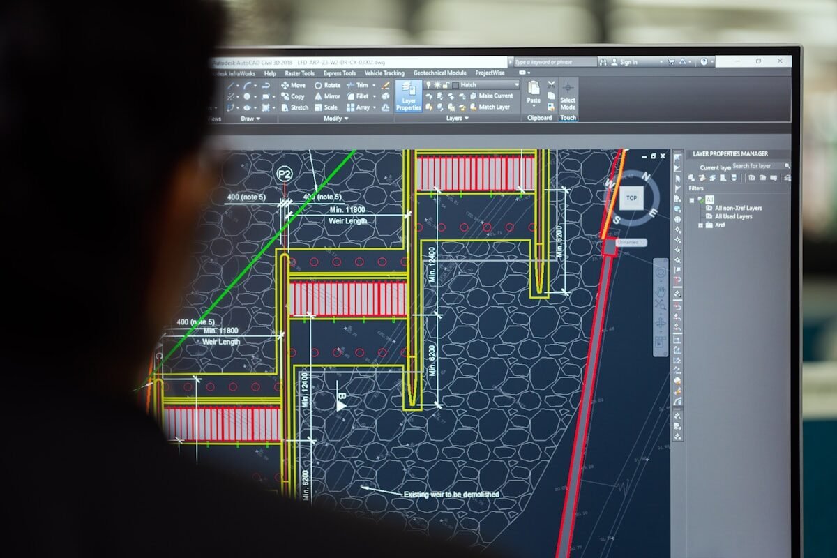
Engineering blueprint and CAD technical drawings of industrial HVAC equipment
Physical Interface Coordination Dimensional Blueprints, Flange Schedules, Nozzle Coordinates & Service Envelopes
01 / Engineering Coordination

Drawings Freeze Interfaces Before Equipment Reaches the Site

A model number does not tell the installer everything. Fans with identical airflow can use different casing lengths or discharge angles; filters can use different depths or seals. Drawings eliminate site clashes.
Engineers reviewing CAD equipment layout drawings on industrial construction site
Drawing Hierarchy

Outline vs. Installation vs. Approved GA

Outline Drawings: Equipment envelope for preliminary MEP layout.
Installation Drawings: Anchor points, curb details, and nozzle orientations.
Approved Project Drawings: Final binding build record for manufacturing.

Centrifugal Fan Discharge Angle Clash

Ordering a 4-72 centrifugal fan without freezing discharge orientation (0° to 270°) results in delivered equipment discharging into plant room walls or columns.

Impact: Costly duct rework & project delays

Omission of Maintenance Clearances

Placing a plate heat exchanger or U-tube storage unit tight against a wall prevents tightening bolt access or axial tube bundle withdrawal during maintenance.

Impact: Unserviceable plant room equipment

Roof Fan Opening Coordination Gap

Cutting DWT roof fan penetrations after roofing waterproofing is completed introduces water-ingress risks and structural compromise. Coordinate from approved drawings early.

Impact: Roof water leakage & civil rework

Replacement Work: Interface vs. Duty

A replacement fan or valve can match physical face-to-face dimensions perfectly while failing completely on aerodynamic pressure or hydraulic Kv authority.

Impact: Check both physical and duty match

The Information Defined on Every Product Drawing

YONGFAN dimensioned drawings provide complete physical transparency across equipment interfaces:

01 Overall Envelope: Width × Height × Length
02 Connection Flanges, Bolt Patterns & Nozzle Schedules
03 Mounting Hole Centers & Foundation Loading
04 Service Access Zones & Withdrawal Clearances
02 / Drawing Directory

Product Drawings by Equipment Family

Explore dimensioned drawings covering fans, roof curbs, filtration racks, cleanroom diffusers, dampers, heat exchangers, and hydronic skids.
Drawing Set 01 · Fans & Roof Units Axial, Mixed, Centrifugal & Roof Curbs

Ventilation Fan & Roof Fan Dimensioned Drawings

Define inlet/outlet flange dimensions, casing length, motor position, airflow direction, centrifugal discharge angle, and roof curb interfaces.

Axial & Mixed Flow: DTF, DTXF, T35-11, SWF, CDZ drawings show casing length, mounting feet, and flexible connection flanges.
Centrifugal (4-72 & SJG): Drawings detail 0°–270° discharge angles, motor slide rails, and access doors.
DWT Roof Fans: Drawings coordinate roof opening, mounting base curb, weather cap dimensions, and drainage.
SDS Tunnel Jet Fans: Drawings detail overall length with 1D/2D silencers, suspension bracket points, and diameter.
DTF / SWF Flanges
Cylindrical duct flange bolt circle diameter & casing length
4-72 Discharge
0°, 45°, 90°, 135°, 180°, 225°, 270° scroll discharge drawings
DWT Roof Curb
Roof opening × curb height × flashing base dimension
SDS Tunnel Jet
Fan body + 1D/2D silencer length & ceiling suspension anchors
Dimensioned engineering drawing of industrial centrifugal fan
Fan Dimensioned Engineering Drawing
Key Drawing Parameters:
  • Flange outer diameter, inner diameter & bolt hole count
  • Motor center height & overall footprint dimensions
  • Service access envelope for motor/belt replacement
  • Mounting baseplate vibration isolator hole centers
Drawing Set 02 · Filters & Terminals W × H × D · Gel-Seal Knife Edge · Frames

Air Filters, Fixing Frames & Cleanroom Terminal Drawings

Coordinate face dimensions, depth, retaining clip arrangements, ceiling grid interfaces, and integrated aerosol test ports.

Filters & Frames: Drawings detail exact W × H × D dimensions (including custom non-standard sizes), header flanges, and fixing frames (610×610, 508×508, 305×610 mm with 20/45/65 mm insert depths).
GCDZ-26Y Gel-Seal: Details 100 mm liquid gel tank profile and ceiling knife-edge penetration depth.
GFK & GCFK Terminals: GFK drawings detail side/top supply spigots and PAO test ports; GCFK details ultra-thin 150 mm shallow depth ceiling integration.

Filter Face & Depth
W × H × D · Header thickness (20 / 25 mm)
Fixing Frames
610×610, 508×508, 305×610 mm (20/45/65 mm insert depths)
Gel-Seal Profile
GCDZ-26Y 100 mm gel channel & knife-edge mating drawings
Cleanroom Terminals
GFK deep diffuser · GCFK 150 mm shallow · FFU ceiling grid
Dimensioned drawing of HEPA filter and cleanroom terminal diffuser
HEPA Filter & Diffuser Box Drawing
Key Drawing Parameters:
  • Ceiling cutout opening & hanging rod bracket locations
  • Duct spigot outer diameter (round) or flange (rectangular)
  • Aerosol challenge port & ΔP test line access positions
  • Filter bank modular grid layout & support structure
Drawing Set 03 · Airside & Scrubbers Actuator Clearance · Media Service Swing

Dampers, VAVs & Chemical Filtration Drawings

Detail damper frame dimensions, blade depth, actuator clearance envelopes, VAV upstream spigots, and chemical scrubber media maintenance doors.

Fire Dampers (FHF / PFHF / PYF): Drawings show duct sleeve length, flange holes, and actuator side clearance (>300 mm required for inspection).
VAV Terminals (YFVAV-S-T100): Details round inlet spigot, rectangular discharge, reheat coil connections, and flow sensor tube positions.
Chemical Units (PSA / PSA-PG / WGP): Drawings detail overall skid dimensions, duct inlet/outlet transitions, and media replacement door swing clearances.

Damper Actuator Side
Left/Right actuator position & >300 mm service envelope
VAV Terminals
Ø125 to Ø400 mm inlet · Discharge plenum · Reheat coil
Chemical Filtration
PSA / PSA-PG double-skin skid dimensions & door swing
WGP Scrubbers
Process duct transitions & exhaust stack discharge interface
Engineering drawing of chemical filtration skid and motorized damper
Chemical Scrubber & Damper GA Drawing
Key Drawing Parameters:
  • Actuator mounting side (LH vs RH) relative to airflow
  • Duct connection flange bolt pitch & thickness
  • Media canister loading access doors & service corridors
  • Control cabinet location & cable entry conduit knockouts
Drawing Set 04 · Thermal & Hydronics Nozzle Schedules · Bundle Withdrawal · Skids

Heat Exchanger, Hydronic Skid & Valve Drawings

Detail plate heat exchanger frame opening zones, U-tube bundle withdrawal clearances, packaged skid footprints, and valve actuator dimensions.

Plate Exchangers (BR Series): Fixed plate, movable plate, tightening bolt area, connection port locations (DN15–DN250), and frame opening service clearance.
Storage Exchangers: U-tube axial bundle withdrawal clearance; floating coil vessel dimensions and floor support points.
Packaged Skids (ZS/ZW/JFHB): Skid footprint, pump centers, make-up tank location, control panel position, and header nozzle schedule.
Valves: FCU valve body lengths, 100X–900X pilot tubing loops, and actuator envelope.

PHE Nozzle Ports
DN15 to DN250 port coordinates · Plate pack tightening span
U-Tube Withdrawal
Axial pull clearance equal to vessel length for bundle removal
Packaged Skids
Skid base dimensions · Pump suction/discharge · Control panel
100X–900X Pilot Loop
Main body face-to-face · Pilot circuit tubing & gauge clearance
Packaged plate heat exchanger skid dimensional drawing
Packaged Heat Exchanger Skid GA Drawing
Key Drawing Parameters:
  • Primary/secondary connection port elevations & ratings
  • Baseplate anchor bolt centers & total operating wet weight
  • Valve face-to-face dimensions (ISO 228 threads vs flanges)
  • Distributor header branch centerline spacing & nozzle sizes
03 / Engineering Governance

Drawings for Replacement Projects & Revision Control

Replacement projects require dual verification: physical interface compatibility and thermodynamic duty matching. Revision control prevents manufacturing discrepancy on repeat orders.
Verification Level Physical / Mechanical Checks Thermodynamic / Electrical Checks Governance Action Action
Interface Match
Duct flange diameter, pipe port centers, face-to-face length, base bolt pattern Actuator envelope, motor frame size, electrical conduit entry location Verify physical fit in existing plant room space Check Fit
Duty Match
Impeller aerodynamic profile, plate chevron angle, filter media pack area Airflow (m³/h) vs Pressure (Pa), Heat Duty (kW) vs ΔP, Valve Kv authority Ensure replacement satisfies operating system requirements Verify Duty
Drawing Revision Freeze
Hole pattern adjustments, nozzle schedule revisions, custom skid length modifications Updated motor kW, changed voltage rating, special sensor/instrument options Freeze approved drawing revision prior to factory fabrication Freeze GA
PDF vs. BIM / CAD Boundary
PDF drawings define binding dimensions, tolerances, and submittal sign-off BIM/CAD models support 3D MEP spatial coordination and clash detection Use PDF for legal submittals; BIM for 3D Revit models BIM Files
04 / Request Protocol

How to Request a Product Drawing

Submit equipment duty schedules and physical interface requirements to receive standard dimensioned drawings or customized project submittal layouts.
STEP 01

Model & Selected Duty

State product model family and selected operating point (airflow, static pressure, heat duty, valve flow rate).

STEP 02

Drawing Type Needed

Specify drawing requirement: Outline/GA drawing for coordination, Installation drawing, or Approved Project drawing.

STEP 03

Connection Orientations

Provide required connection angles: centrifugal discharge angle (0°–270°), PHE nozzle schedule, or VAV actuator side.

STEP 04

File Format Required

Indicate required format: PDF dimensioned submittal drawing, DWG 2D CAD layout, or 3D BIM coordination model.

Engineering Handoff

Request Product Drawings & Layouts

Submit your equipment dimensional requirements or existing installation drawings. YONGFAN drafting specialists will issue verified CAD / PDF submittals.

1. Exact Product Model & Selected Duty
2. Drawing Type (Outline, Installation, Approved GA)
3. Flange Connection Sizes & Bolt Standards
4. Centrifugal Fan Discharge Orientation (0°–270°)
5. Damper Actuator Mounting Side (Left vs Right)
6. Packaged Skid Nozzle Orientation & Footprint
7. Existing Plant Room Photographs (for Retrofits)
8. Required File Format: PDF, DWG (2D), or BIM
05 / Drafting Quality Assurance

Drawing Precision & Interface Verification

Automated CAD/CAM integration, dimensional tolerance controls, and submittal revision locking prior to production.
CAM Precision

NC Laser & Tooling Integration

Approved project drawings interface directly with CNC plasma cutters and automated press tooling to ensure exact dimensional matching.

Interface QA

Flange & Bolt Hole Verification

Cylindrical and rectangular flanges are checked against standardized duct and pipe drilling tables to prevent site bolting mismatches.

Clearance QA

Maintenance Envelope Check

Drawings incorporate verified withdrawal envelopes for filter elements, PHE plate packs, and U-tube bundles to ensure serviceability.

Revision QA

Strict Revision Locking

Factory production orders reference locked drawing revision numbers, preventing discrepancies between approved submittals and delivered goods.

06 / Engineering Knowledge

Product Drawings Frequently Asked Questions

Technical answers to key questions regarding drawing types, catalog dimensions, custom sizes, and BIM availability.

Is a drawing the same as a Technical Data Sheet?

No. A TDS explains technical performance, limits, and test standards. A drawing defines physical dimensions, bolt patterns, connections, and service clearances.

Can I use a catalog dimension for final coordination?

Always use the latest approved or model-specific drawing for final site coordination. Catalog dimensions represent standard baseline configurations.

Can YONGFAN provide dimensioned fan drawings?

Yes. YONGFAN issues dimensioned drawings and performance curves for axial (DTF), mixed-flow (SWF), centrifugal (4-72), roof (DWT), and tunnel fans (SDS).

Are custom filter dimensions supported on drawings?

Yes. YONGFAN filter documentation supports non-standard W × H × D dimensions. The final custom filter and fixing frame are coordinated on the project drawing.

Why do I need maintenance clearance on a drawing?

Equipment may physically fit into a plant room but still be impossible to maintain. Plate removal, filter change, belt tensioning, and bundle withdrawal require dedicated clearance.

Can a drawing prove that a replacement fan is equivalent?

No. It proves physical interface compatibility. The aerodynamic airflow-pressure duty and motor electrical ratings still require technical confirmation via TDS.

Can I request a project-specific packaged skid layout?

Yes. YONGFAN packaged heat exchangers and booster skids support project-specific nozzle orientations, pump arrangements, and footprint configurations.

Does every YONGFAN product have a 3D BIM file?

Where 3D BIM models are required for Revit coordination, request the model file for your selected product family through the separate BIM / CAD Files page.

07 / Drawing Boundaries

Product Drawings Define Equipment Envelope

Understanding drawing boundaries ensures clear engineering governance across MEP plant coordination and construction phases.
Boundary 01 / Factory Supply

Equipment Boundary

YONGFAN drawings define the supplied equipment envelope and connection flanges; connecting ductwork and piping design belong to MEP consultants.

Boundary 02 / Structural Design

Foundation Reinforcement

YONGFAN drawings state equipment operating wet weights and anchor bolt centers; civil floor slab load-bearing design remains structural engineer scope.

Boundary 03 / Electrical Feeder

Field Wiring Routing

Drawings detail terminal junction box locations; external conduit routing, cable tray sizing, and MCC panel locations belong to electrical contractor scope.

Boundary 04 / Performance Proof

Thermodynamic Verification

A drawing proves physical interface compatibility; thermodynamic and aerodynamic performance verification requires the certified TDS and test report.

08 / Drafting Handoff

Request a Product Drawing

Send your candidate model number, connection orientation requirements, and project reference — YONGFAN drafting engineers will provide certified PDF dimensioned drawings and 2D CAD layouts.

Ventilation Fan Dimensioned GA DWT Roof Curb Drawings Filter Frames & Cleanroom Diffusers Fire Damper Actuator Clearances PHE Nozzles & Tightening Dimensions Packaged Skid Footprints & Baseplates
Engineers reviewing CAD product drawings and architectural coordination plans
YONGFAN Technical Drafting Support
Dimensioned GA drawings, flange coordination & certified project submittals.