
YONGFAN HVAC - Premium Header
Engineered HVAC & Industrial Air Systems
YONGFAN HVACYOFAN HVAC Home
Heat Exchange Equipment | Plate, Packaged, Tube, Storage & Mixing | YONGFAN
Thermal Engineering · 5 Equipment Families · 0.14–21 MW

Heat Exchange Equipment: Matched to Duty, Temperatures & Water Chemistry

Heat exchange equipment must match duty, temperature program, pressure, water chemistry and maintenance strategy; the wrong architecture increases fouling, footprint, or plant-room complexity.

Compare YONGFAN plate, packaged skid, enhanced tube, storage, and direct-mixing heating equipment across heating capacities (0.14–21 MW), pressures (up to 2.5 MPa), approach temperatures (down to 1 °C), and metallurgy (316L, Titanium TA1, Hastelloy, Copper).

5 Families PHE · Skid · Tube · Buffer · Mix
Capacity Span 0.14 – 21 MW
Approach ΔT Down to 1 °C
Pressure Classes 1.0 / 1.6 / 2.5 MPa
YONGFAN gasketed plate heat exchanger
Hydronic Thermal Transfer District Substations · Process Thermal Transfer · Domestic Hot Water
01 / System Selection

Heat-Transfer Problems Begin When Duty Is Reduced to One Capacity Number

A heat exchanger can be rated for the required megawatts and still fail if the four terminal temperatures, allowable pressure drop, or water hardness are overlooked.
YONGFAN floating-coil heat exchanger
Thermal Driving Force

Why 1 MW Is Not a Standard Hardware Size

Per ASHRAE Heat Transfer guidance, log mean temperature difference (LMTD), chevron angle, and channel velocity determine actual heat-transfer surface area.

Ignoring Temperature Program

1 MW transferring steam to 85 °C water requires vastly different surface area than 1 MW transferring 95/70 °C water to a 45/55 °C floor-heating circuit.

Impact: Secondary loop misses target supply temperature

Instantaneous vs. Buffer Mismatch

Hotels with morning shower peaks require storage buffering. An instantaneous exchanger must be drastically oversized to follow peaks directly.

Impact: Hot water runs out during morning peak draw

Water Chemistry & Metallurgy

Standard 304/316 stainless plates corrode rapidly on seawater, brine, or high-chloride water. Titanium TA1 or Hastelloy must be matched to fluid chemistry.

Impact: Plate pinhole perforation & cross-circuit leaks

Fouling & Scale Resistance

Hard domestic water causes plate channel scaling. Floating-coil or withdrawable U-tube vessels provide self-descaling and mechanical cleanability.

Impact: Thermal degradation & high maintenance downtime

Five Decision Inputs Before Equipment Sizing Begins

Verified against GB150 & GB151 pressure-vessel and heat-exchanger standards.

01 Primary & Secondary Temperatures (4 Points)
02 Total Heat Load (kW / MW) or Peak Draw (L)
03 Allowable Pressure Drop on Both Sides
04 Working Pressure & Water Analysis (Chlorides/pH)
02 / Portfolio Showcase

Choose the Heat-Exchange Family Before the Model

Detailed overview of YONGFAN’s five core thermal architectures: gasketed plates, packaged skids, turbulent tubes, storage vessels, and high-rise mixing units.
01 · Plate Heat Exchangers 0.2 to 500 m² · 4 to 900 m³/h

BR Series Gasketed Plate Heat Exchangers

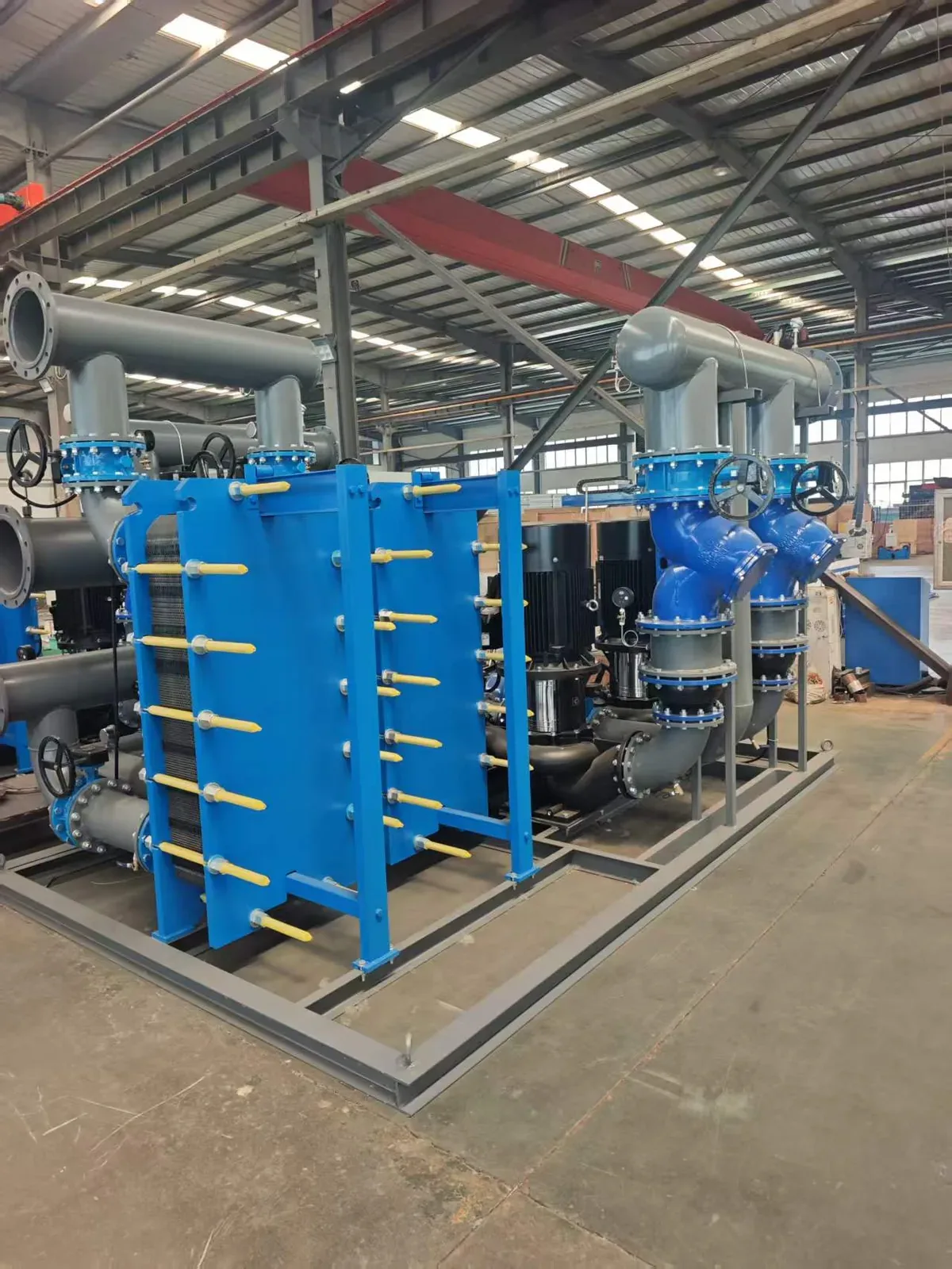
Compact, serviceable two-loop heat transfer. Documented per-plate areas from 0.02 to 1.3 m², connections DN15–DN250, and design pressures up to 2.5 MPa. Full counter-flow approach temperatures down to 1 °C. SUS304/316L/Titanium TA1/Hastelloy plates; EPDM/NBR/Fluororubber gaskets.

Assembly Area
0.2 – 500 m²
Max Flow Rate
4 – 900 m³/h
Design Pressure
1.0 / 1.6 / 2.5 MPa
Wide-Gap Option
BRb0.5 / 0.7 / 0.9 (Particulates)
Primary Use Cases

Central cooling stations, district-heating substations (when plant equipment is separate), heat pumps, and aggressive chemical process cooling.

02 · Packaged Units 0.21 to 21 MW · Complete Skid

Packaged Plate Heat Exchange Units (ZS & ZW Series)

Integrated plant-room skid combining plate exchanger, dual/triple circulation pumps, automated make-up system (ZS VFD or ZW expansion device), valves, sensors, and PLC control cabinet. Covers 3,000–300,000 m² heating area across 60/85 °C (NB) and 45/55 °C (K(D)B) programs.

Capacity Range
0.21 – 21 MW per skid
Primary Source
Steam ≤0.4 MPa or Water 95/70 °C
Make-Up System
ZS (VFD) or ZW (Expansion)
Secondary Loops
60/85 °C (NB) · 45/55 °C (KB)
Primary Use Cases

District heating substations, commercial building central mechanical rooms, and industrial park energy centers requiring factory-tested skids.

03 · Tube Heat Exchangers 0.35 to 5.6 MW · Enhanced Tubes

JFSW Double-Thread Turbulent Heat Exchangers

Shell-and-tube construction with double-thread copper or stainless tubes that induce boundary-layer turbulence on both inside and outside tube walls. Documented on 0.2 MPa steam for heating (70→95 °C), A/C (50→60 °C), and domestic hot water (5→60 °C). Vertical or horizontal mounting.

Capacity Range
0.35 – 5.6 MW per unit
Shell Classes
200 – 700 (Ø219 to Ø720 mm)
Tube Metallurgy
Double-Thread Copper / Stainless
Orientation
Vertical (Headroom) / Horizontal
Primary Use Cases

Steam-to-water heating, industrial water-water loops, and mechanical rooms where plant maintenance practices prefer shell-and-tube access.

04 · Storage Heat Exchangers 100 to 15,000 L · Peak Buffering

U-Tube & Floating-Coil Storage Heat Exchangers

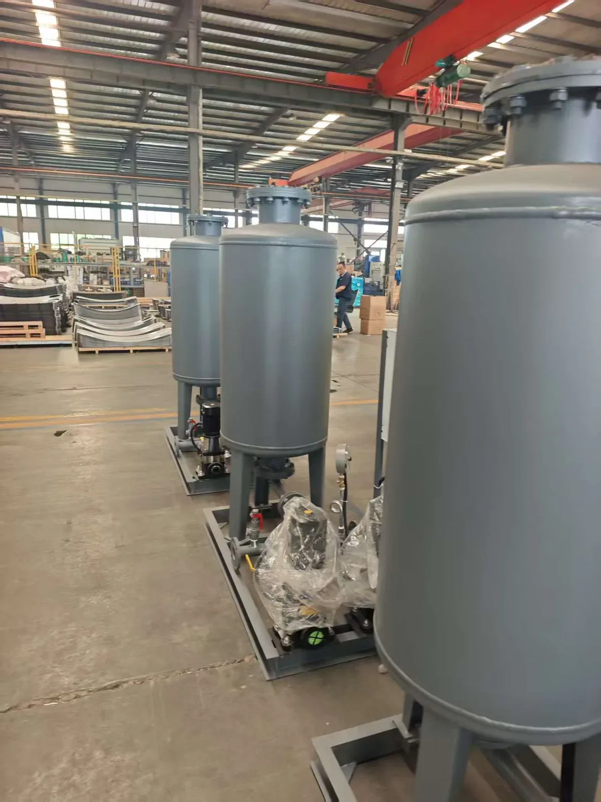
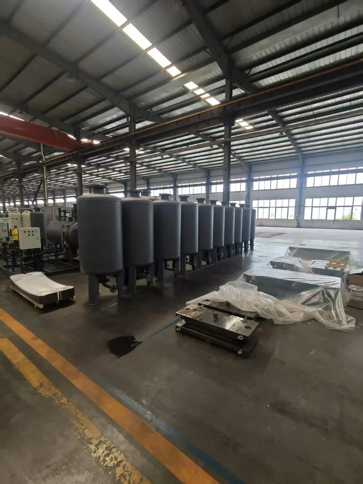
Combines thermal transfer with stored hot-water volume. U-tube units feature flanged, withdrawable bundles for manual cleaning (up to 10 MW). Floating-coil units use thermal coil movement for automatic scale-cracking, ideal for hard water, solar thermal, and heat pumps.

Vessel Volumes
100 – 15,000 L (Std 200–10,000 L)
Capacity Range
21 – 1,045 kW steam · 10–528 kW water
Pressure Rating
1.0 / 1.6 MPa (High Press 2.5 MPa)
Bundle / Coil
Copper, 304, 316L, 316Ti
Primary Use Cases

Hotels, hospitals, schools, pools, and residential complexes with sharp domestic hot-water draw peaks that exceed boiler recovery rates.

05 · Direct-Mixing Units 0.14 to 4.2 MW · 20–60 m Elevation

High-Rise Direct-Mixing Heating Units

Connects high- and low-zone water circuits directly through pressure-reducing valves, pumps, and PLC controls without an intermediate heat exchanger. Bridges 20–60 m hydrostatic elevation differences (0.5–1.0 MPa system pressure) across radiator (25 K ΔT) and floor heating (10 K ΔT).

Heat Load
0.14 – 4.2 MW per unit
Elevation Span
20 – 60 m Building Height
Circulation Flow
4.8 – 360 m³/h
Control Modes
Manual, Automatic & Remote PLC
Primary Use Cases

High-rise residential and commercial heating zones looking to eliminate intermediate plate exchangers, rooftop buffer tanks, or separate high-zone boilers.

03 / Selection Routing

Heat Exchange Family Comparison Matrix

Cross-reference all five YONGFAN heat exchange product families by primary engineering role, published capacity boundary, and first selection input.
Product Family What It Solves Published Range Boundary First Input to Confirm Action
Plate Heat Exchangers Compact, serviceable heat transfer between two circuits 4–900 m³/h · Up to 500 m² · 1.0/1.6/2.5 MPa Primary/secondary temperature programs & fluid chemistry Configure PHE
Packaged Heat Exchange Units Complete exchanger, pump, make-up & PLC control skid 0.21–21 MW · 3,000–300,000 m² heating area Heat source (steam/water) & total calculated heating load Configure Skid
Tube Heat Exchangers Enhanced turbulent tube steam-water or water-water transfer 0.35–5.6 MW · Shell classes 200–700 Duty temperature program (Heating, A/C, or DHW) Configure Tube
Storage Heat Exchangers Heat transfer plus domestic hot-water peak buffering 100–15,000 L · U-tube up to 10 MW Peak hot-water draw volume (L) & recovery window (min) Configure Storage
Direct-Mixing Heating Units High-rise heating zone connection without intermediate PHE 0.14–4.2 MW · 20–60 m elevation difference Zone elevation height (m) & terminal ΔT (25 K vs 10 K) Configure Mixing
04 / Procurement Protocol

Information Required for Thermal Equipment Sizing

Provide four fluid temperatures, available heat source, working pressures, allowable pressure losses, and water analysis.
STEP 01

Primary Heat Source

Steam pressure (MPa) or boiler/district water supply & return temperatures (°C).

STEP 02

Secondary Duty & ΔT

Target supply/return temperatures (°C) and total thermal load in kW or MW.

STEP 03

Pressure & ΔP Allowance

Maximum working pressure and allowable pressure drop (kPa) on both fluid circuits.

STEP 04

Water Quality Analysis

Chloride content (ppm), hardness, and pH to confirm plate/tube metallurgy.

Engineering Handoff

Submit System Data for Thermal Equipment Sizing

YONGFAN engineers will calculate heat transfer area, check flow velocity, and provide dimensioned GA drawings.

Primary & Secondary 4 Temperatures
Total Thermal Capacity (kW / MW)
Allowable Pressure Drop ΔP (kPa)
Water Hardness / Chlorides (ppm)
Peak Hot Water Draw (Storage Units)
Elevation Height (Direct Mixing)
05 / Manufacturing Verification

Hydrostatic Integrity & Leakage Checks

YONGFAN manufactures and tests heat exchange equipment under GB150 & GB151 standards with 1.25× hydrostatic pressure testing on every unit.
Pressure QA

1.25× Hydrostatic Test

Every plate pack, shell, tube bundle, and storage vessel undergoes hydrostatic pressure testing at 1.25× design pressure.

Leakage QA

Cross-Leak Testing

Single-side pressurization verifies zero cross-contamination between primary heat medium and secondary potable/heating circuits.

Skid QA

Pre-Piped Workshop Assembly

Packaged skids are assembled on structural steel bases with pumps, valves, instruments, and PLC wiring fully pre-tested.

Materials QA

Mill Certificate Traceability

Plate and tube metallurgy (316L, TA1, Hastelloy, Copper) is verified against raw material certificates before fabrication.

Bespoke Engineering: Duty calculation sheets, GA layout drawings, and 3D CAD models supplied with quotation. Trade Terms: EXW, FOB, CIF, and DDP export logistics with heavy-duty export crating.
06 / Engineering Knowledge

Heat Exchange Equipment FAQ

Direct engineering answers regarding substation selection, storage sizing, high-rise direct mixing, and water quality.

Which family should I use for a district-heating substation?

Start with Packaged Heat Exchange Units when pumps, make-up, and controls are needed on one skid. Use Plate Heat Exchangers if pumps are specified separately.

Which product handles hard domestic hot water?

Review Floating-Coil Storage Heat Exchangers. Thermal expansion and contraction cycles naturally crack scale from the coil surface without chemical dosing.

When should I choose the U-tube storage design?

Choose U-Tube Storage Heat Exchangers when site maintenance protocol prefers withdrawing the complete flanged bundle for direct inspection and replacement.

What is the difference between a packaged skid and a bare plate exchanger?

A packaged skid includes circulation pumps, variable make-up or expansion devices, valves, sensors, and pre-wired PLC control cabinets.

Which family connects high- and low-zone heating in tall buildings?

Review Direct-Mixing Heating Units (20–60 m elevation) when eliminating intermediate plate exchangers or rooftop buffer tanks is desired.

What information should I provide for equipment selection?

Heat source (steam/water), primary & secondary temperatures, thermal load (kW/MW), working pressure, and water chemistry (chlorides/hardness).

07 / Application Boundaries

Heat Exchange Engineering Boundaries

Matching the right thermal architecture to specific physical and hydraulic requirements.
Boundary 01 / Metallurgy

Chloride Exposure

Do not use standard stainless plates on seawater or brine without upgrading to Titanium TA1 or Hastelloy.

Boundary 02 / Domestic Peaks

Do Not Undersize Storage

Instantaneous exchangers cannot buffer peak domestic hot water draw without excessive boiler firing capacity.

Boundary 03 / Hydraulic Isolation

Direct Mixing Limits

Direct mixing connects fluid circuits; use plate heat exchangers when full hydraulic circuit isolation is required.

Boundary 04 / Temperature Program

ΔT Drives Water Flow

Floor heating (10 K ΔT) moves 2.5× more water flow than radiator heating (25 K ΔT) for the same MW thermal load.

08 / Engineering Handoff

Select the Right Heat Exchange Equipment for Your System

Send your thermal load, temperature program, working pressure, and water chemistry. YONGFAN application engineers will verify heat-transfer surface area, pressure drop, and provide complete submittal drawings.

Capacity: 0.14–21 MW 4 Terminal Temperatures 1.0 / 1.6 / 2.5 MPa Classes 316L / TA1 / Hastelloy / Copper Packaged Skids (ZS / ZW) 1.25× Hydrostatic Tested
YONGFAN storage-type U-tube heat exchanger
Direct Application Engineering Support
LMTD heat transfer calculations, pressure drop curves & GA submittals.