
YONGFAN HVAC - Premium Header
Engineered HVAC & Industrial Air Systems
YONGFAN HVACYOFAN HVAC Home
Installation Manuals | HVAC Components | YONGFAN
Mechanical Mounting & Site Commissioning

Installation Manuals: Mounting, Wiring & Commissioning

Installation manuals help contractors, commissioning teams and facility engineers translate the approved YONGFAN product selection into a correct physical installation.

Learn step-by-step procedures for fan rotation checks, flexible duct connectors, roof curbs, filter gasket compression, knife-edge gel seals, VAV upstream duct straight runs, plate heat exchanger frame opening clearances, and valve actuator orientation.

Fan Alignment Flexible Connectors & Jog Test
Filter Sealing Zero-Bypass Gasket & Gel Seating
Thermal Piping PHE Clearances & Gradual Warmup
Valve Actuators Pipe Flushing & Upright Mounting
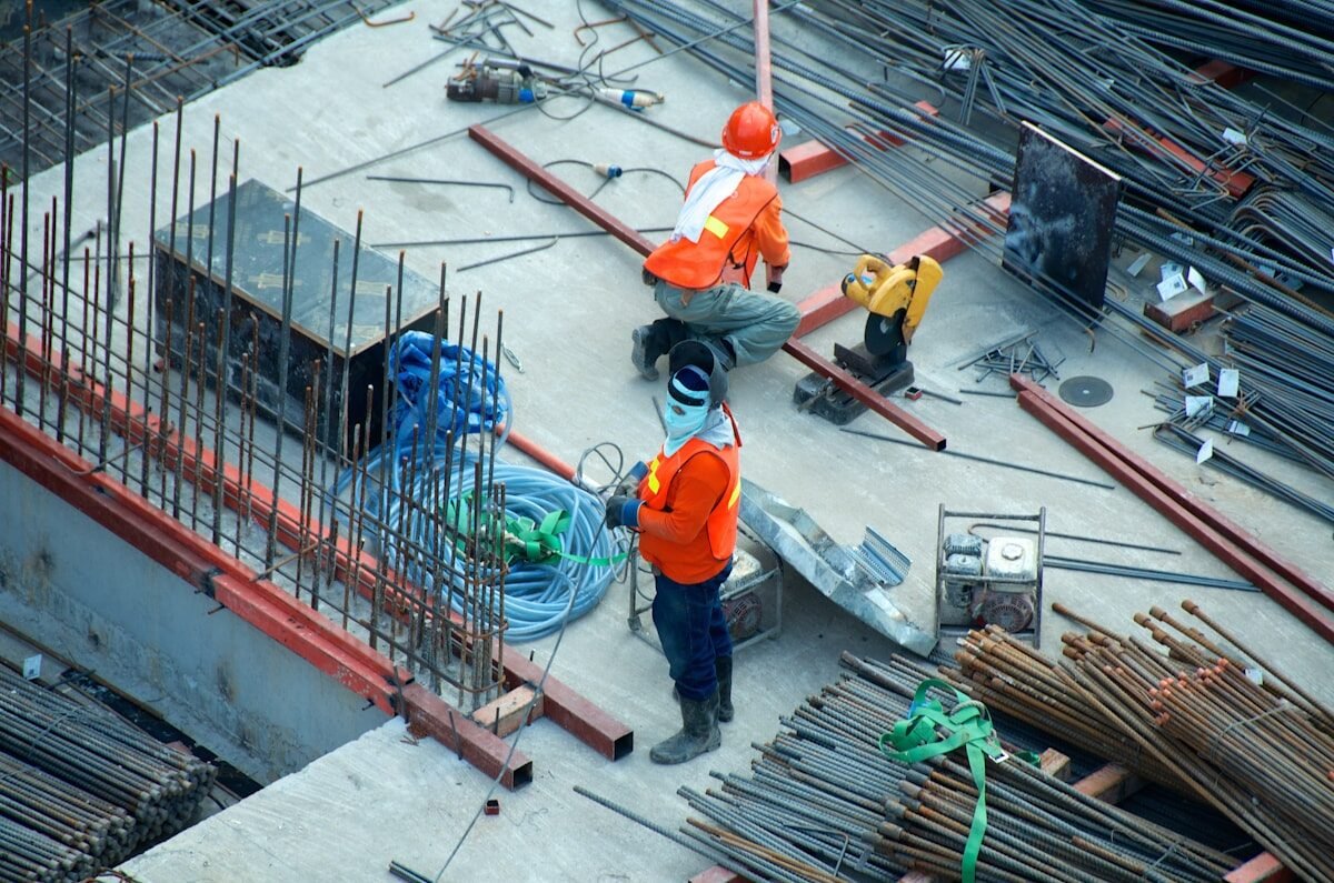
Contractor installing industrial ventilation fan and ductwork on construction site
Site Execution Guidelines Duct Alignment, Gasket Compression, Wiring Verification & Commissioning Procedures
01 / Installation Fundamentals

Installation Starts After Product Configuration Is Frozen

A correctly selected product can still fail if installed with disturbed inlet conditions, poor gasket seating, inverted actuators, or uncoordinated roof curbs.
Mechanical room piping, pumps, and valves during installation and commissioning
Receiving Protocol

Verify Nameplates Before Anchoring

Check voltage, motor kW, pressure class, filter efficiency grade, airflow direction arrows, and option codes against the approved submittal drawing before mechanical mounting.

Reverse Fan Motor Rotation

Energizing a 3-phase fan in reverse rotation moves some air but causes massive airflow/pressure loss and motor overheating. Always jog the motor to verify rotation.

Impact: 50% airflow shortfall & motor overload

Inverted Valve Actuator Orientation

Mounting electric valve actuators upside down allows pipeline condensation to drain directly into the actuator electronics, causing short circuits.

Impact: Actuator electronic failure & water damage

Handling Filter Media Directly

Carrying delicate HEPA or bag filters by pressing on the media pack causes micro-tears and potting delamination, leading to immediate validation failure.

Impact: Failed in-situ cleanroom scan testing

Omitting Pipeline Flushing

Failing to flush hydronic piping before commissioning control valves allows welding slag and pipe debris to score ball/plug seats and jam actuators.

Impact: Seat leakage & actuator mechanical binding

The Four Pre-Installation Verifications

Execute these checks on delivered equipment before fixing hardware into place:

01 Nameplate Voltage, Phase & Model Match
02 Transport Damage & Free Impeller Rotation Check
03 Airflow / Fluid Flow Arrow Alignment
04 Service & Maintenance Withdrawal Clearances
02 / Installation Procedures

Equipment-Specific Installation Guidelines

Review detailed mounting, piping, wiring, and clearance instructions tailored to each YONGFAN product family.
Procedure 01 · Fans & Roof Units Aerodynamic Alignment · Curb Weatherproofing

Ventilation Fans & Roof Fans Installation

Correct fan mounting preserves aerodynamic efficiency, prevents vibration transmission, and protects motors from abnormal mechanical loading.

In-Line Axial & Mixed-Flow (DTF / SWF): Install with flexible canvas/silicone connectors at inlet and outlet. Never force ductwork into alignment by pulling against fan flanges — duct supports must carry independent loads.
Rotation Check: Briefly jog the motor to confirm impeller rotation matches the directional casing arrow. For reversible tunnel fans (SDS-R), verify reversal control logic.
Belt-Driven Fans: Check pulley laser alignment, set belt tension, and ensure belt guards allow service access.
Roof Fans (DWT Series): Mount level on pre-coordinated roof curbs with continuous weather-tight flashing and drainage before roofing seal is finalized.
Flexible Connectors
DTF/SWF in-line flexible sleeves; prevent vibration transmission
Motor Jog Test
Briefly energize to confirm rotation matches casing arrow
Belt Tension
Align pulleys with straightedge; prevent belt slip & bearing load
DWT Roof Curbs
Coordinate roof penetration before roofing waterproofing
Contractor checking belt alignment on industrial ventilation fan
Fan Flexible Connection & Motor Alignment
Key Checks:
  • Verify impeller spins freely by hand before power-up
  • Avoid sharp elbows immediately at fan suction
  • Ensure dual-speed wiring matches terminal diagram
  • Verify emergency 280°C fire power supply cabling

Procedure 02 · Filters & Cleanroom Zero Bypass · Gel-Seal Seating

Air Filters & Cleanroom Terminal Equipment Installation

A filter only delivers its rated efficiency when all airflow passes through the media pack without frame bypass.

Handling Care: Handle filters only by the outer frame. Never press on pleats or rest tools on filter faces.
Gasket Seating: Inspect neoprene gaskets for uniform compression without gaps, tears, or over-torqued deformation.
Gel-Seal Terminals (GCDZ-26Y): Ensure ceiling knife-edge blades are straight, clean, and fully embedded into the liquid polyurethane gel channel.
Bag Inflation: Verify ZF bag pockets have >650 mm downstream clearance to expand freely without touching coils or walls.
Replacement Clearance: Provide adequate service door clearance for filter withdrawal.

Frame Match
Verify 20 / 45 / 65 mm insert depth matches fixing frame
Gel-Seal Seating
GCDZ-26Y knife-edge blade fully submerged in gel channel
Bag Pocket Clearance
Ensure 600 mm bag pockets inflate freely without sagging
Validation Ports
GFK housings: connect PAO aerosol challenge & ΔP tubing
Technician seating gel seal HEPA filter into cleanroom ceiling diffuser
GCDZ-26Y Gel-Seal Knife-Edge Seating
Key Checks:
  • Verify airflow direction arrow points downstream
  • Clean and wipe fixing frame channels before seating
  • Perform room-side aerosol challenge per ISO 14644-3
  • Record initial clean differential pressure baseline
Procedure 03 · Dampers & VAVs Thermal Action · Straight Duct Runs

Fire Dampers & VAV Terminal Installation

Preserving fire safety closure logic and ensuring accurate pressure-independent dynamic airflow sensing across zone terminals.

Damper Orientation: Mount fire/smoke dampers (FHF / PFHF / PYF) without twisting the frame. Frame distortion causes blade binding. Keep actuators accessible for maintenance — never bury actuators behind permanent ceilings without access hatches.
VAV Terminals (YFVAV-S-T100): Maintain straight duct length (minimum 3–5 duct diameters) upstream of the inlet flow sensor to avoid turbulent airflow measurement errors. Connect controller pressure sensing tubes securely.
Multi-Outlet Plenums (YF-MOA): Coordinate branch spigot count and locations with ceiling diffuser layouts.

Frame Squareness
Support ductwork independently to prevent damper casing twist
Actuator Access
Provide >300 mm clearance around thermal fuses and motors
VAV Straight Duct
3–5 duct diameters straight run upstream of flow sensor
Reheat Coil Flush
Flush hot water reheat piping before connecting control valves
Fire damper and VAV terminal installation in commercial ductwork
Fire Damper & VAV Terminal Installation
Key Checks:
  • Verify normal blade position (FHF/PFHF NO vs PYF NC)
  • Test thermal fuse release and microswitch feedback
  • Connect DDC BMS Modbus/BACnet communications
  • Ensure YF-MOA branch balancing dampers are set
Procedure 04 · Thermal & Hydronics Pipeline Flushing & Thermal Warmup

Heat Exchangers, Hydronics & Valve Installation

Mechanical support, piping flushing, thermal expansion avoidance, and correct actuator electrical termination across plant rooms.

Plate Heat Exchangers (PHE): Mount with adequate clearance to open the frame and withdraw plates. Support connected pipework independently to prevent nozzle stress. Vent all air and bring system up to temperature gradually.
U-Tube & Floating Coil Storage: Provide axial clearance to pull the tube bundle. Ensure foundation supports operating vessel weight full of water.
Valves & Actuators: Flush pipelines to remove debris before mounting. Apply wrench force to valve body flats — never twist the actuator. Never mount actuators upside down. Use PTFE tape on threads sparingly without entering flow passages.

PHE Clearances
Preserve frame opening space equal to plate pack length
Pipeline Flushing
Flush all headers and loops before installing control valves
Actuator Orientation
Horizontal or upright only; strictly prohibit inverted mounting
Plant Skids (JFDY/JFHB)
Level skid base, align pump couplings, and connect sensors
Contractor connecting hydronic piping and control valves on plate heat exchanger
PHE Piping Connection & Valve Installation
Key Checks:
  • Verify fluid flow direction arrows on valve bodies
  • Check electrical wiring against voltage rating
  • Slowly pressurize and vent air to avoid water hammer
  • Verify JFDY expansion pre-charge pressure before filling
03 / Field Verification

Commissioning Should Verify the Installed System, Not Only the Part

A factory test proves product baseline quality. On-site commissioning verifies how equipment performs when integrated into actual building ductwork and piping.
Equipment Category Pre-Start Verification Operational Run Checks Safety & Control Interlocks Action
Ventilation Fans
Impeller free rotation, base anchor torque, duct flexible connectors Motor running current (A), vibration velocity, delivered airflow/static pressure Thermal overload trip, VFD ramp times, emergency smoke fire interlocks Fan QA
Air Filtration
Gasket alignment, frame cleanliness, gel knife-edge depth, media condition Initial clean ΔP baseline recording, air velocity uniformity across bank In-situ PAO aerosol challenge testing (ISO 14644-3), ΔP alarm switches Filter QA
Fire & VAV Dampers
Frame squareness, free blade travel by hand, straight upstream duct run Actuator drive stroke time, VAV minimum/maximum airflow calibration 70°C/280°C thermal fuse release, BMS alarm feedback, spring-return fail close Damper QA
Heat Exchangers
Plate pack tightening dimension (A-dim), pipe nozzle support, air venting Primary/secondary fluid temperatures, flow balance, clean pressure loss Slow thermal warmup, overpressure relief valve setting, leak inspection Thermal QA
Control & Pilot Valves
Pipeline flushed clean, Y-strainer installed, upright actuator orientation 0–10V modulating response, pilot regulator pressure setting (200X/500X) Bubble-tight seat shut-off, auxiliary switch end-position feedback to BMS Valve QA
04 / Request Protocol

How to Request an Installation Manual

Download verified installation guides or request model-specific wiring schematics and mounting submittals from YONGFAN technical support.
STEP 01

Model & Order Reference

Provide exact equipment model number, serial number, or sales order reference from the nameplate.

STEP 02

Voltage & Configuration

State supply voltage (380V/220V/24V), control mode (VFD, dual-speed, modulating), and ordered options.

STEP 03

Installation Orientation

Indicate physical mounting: horizontal, vertical, ceiling-suspended, roof curb, or plant room skid.

STEP 04

Project Language

Specify preferred documentation language and any market-specific commissioning checklists required.

Support Handoff

Request Installation Support

Need wiring diagrams, torque specifications, or remote commissioning guidance? YONGFAN application support engineers are available to assist your site installation team.

1. Exact Model Number & Serial Number
2. Motor Voltage, Frequency & Wiring Diagram
3. Mounting Orientation & Support Interface
4. Filter Seal Type (Neoprene vs Polyurethane Gel)
5. Actuator Signal Voltage & Spring Return Fail State
6. Fire Damper Sequence & BMS Microswitch Wiring
7. Site Photo of Installed Space (for Retrofits)
8. Project Country & Manual Language
05 / Site Quality Assurance

Correct Installation Protects Selected Performance

Bridging technical equipment selection with reliable mechanical mounting, electrical wiring, and commissioning governance.
Mechanical QA

Zero Casing Distortion

Proper independent duct and pipe hanging prevents transferring heavy external loads onto fan casings, damper frames, or PHE nozzles.

Electrical QA

Verified Terminal Wiring

Clear wiring diagrams ensure correct phase rotation, motor thermal protection interlocks, and 0–10V BMS actuator modulation.

Hydraulic QA

Clean Loop Commissioning

Mandatory line flushing, air venting, and slow initial thermal warmup protect valve seats, gaskets, and plate packs from damage.

Technical Support

Remote Engineering Support

YONGFAN application specialists provide remote troubleshooting and technical advice during contractor installation and startup.

06 / Engineering Knowledge

Installation Manuals Frequently Asked Questions

Answers to key technical questions regarding drawings vs manuals, actuator orientation, flexible connectors, and service clearances.

Is the installation manual the same as the product TDS?

No. A TDS describes technical performance limits and test standards. An installation manual explains physical mounting, electrical wiring, piping connections, startup, and maintenance.

Should I install equipment from the generic catalog drawing?

No. Always use the approved project dimensioned drawing and model-specific installation manual. Catalog dimensions represent standard baseline configurations.

Can I change the installation orientation in the field?

Only if documented as permissible. Fan discharge direction, valve actuator orientation, filter withdrawal side, and skid piping connections directly impact operation.

Do in-line duct fans need flexible connectors?

Yes. YONGFAN DTF and SWF in-line duct fans should be installed with flexible sleeve connectors at inlet and outlet to isolate vibration from the ductwork.

Can an electric valve actuator be installed upside down?

No. YONGFAN electric valve instructions specifically prohibit inverted actuator mounting below the horizontal centerline to prevent water damage from condensation.

Why does filter withdrawal clearance matter during installation?

Filters are consumable items. If maintenance clearances are obstructed by adjacent pipes or walls, replacing filters requires costly duct dismantling.

Do I need service clearance around a plate heat exchanger?

Yes. Gasketed plate exchangers require axial frame clearance equal to the plate pack to slide and inspect plates; U-tube storage units need room to pull the tube bundle.

Can YONGFAN provide on-site or remote installation support?

Yes. YONGFAN product documentation describes installation guidance, remote video troubleshooting, and technical assistance for contractor commissioning teams.

07 / Installation Boundaries

Installation Scope Ends at the Supplied Component

Understanding system boundaries ensures clear delineation of engineering responsibilities across contractor site execution.
Boundary 01 / Contractor Scope

Field Labor Execution

YONGFAN provides equipment and manuals; physical rigging, mounting, pipe welding, and electrical wiring are executed by licensed site contractors.

Boundary 02 / Structural Anchors

Seismic & Civil Anchors

YONGFAN supplies mounting brackets; structural calculation of roof curbs, seismic spring isolators, and concrete inertia pads belongs to civil engineers.

Boundary 03 / Electrical Supply

Feeders & Disconnects

YONGFAN supplies terminal junction boxes; external power distribution panels, branch circuit breakers, and local disconnect switches belong to electrical scope.

Boundary 04 / Permitting

Building Code Sign-Off

YONGFAN supplies product test certificates; local municipal building authority inspections and fire marshal sign-offs remain general contractor scope.

08 / Installation Handoff

Request an Installation Manual

Send your equipment model number, order reference, or installation inquiry — YONGFAN technical application specialists will provide verified installation manuals, wiring schematics, and startup checklists.

Ventilation Fan Mounting & Jog Test Filter Zero-Bypass Gasket Seating GCDZ-26Y Gel-Seal Knife-Edge Fire Damper Thermal Logic PHE Frame Service Clearances Valve Actuator Upright Wiring
Engineers reviewing HVAC installation manuals and mechanical site drawings
YONGFAN Technical Installation Support
Mounting instructions, wiring verification & certified commissioning guidelines.