YONGFAN HVAC - Premium Header
Engineered HVAC & Industrial Air Systems
YONGFAN HVACYOFAN HVAC Home
Pressure Stabilizing & Expansion Units | YONGFAN
Packaged Hydronic Skid · JFWP Series · 48–480 m³

Pressure Stabilizing & Expansion Units: Matched to Closed-Loop Water Volume

Pressure stabilizing and expansion units must match closed-loop water volume, pressure limits, make-up rate and expansion strategy; wrong sizing can cause pump cycling, relief discharge or low-pressure faults.

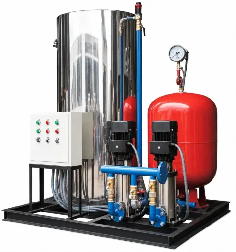
YONGFAN JFWP Packaged Skids integrate automated make-up pumps, bladder pressure stabilization, thermal expansion management, overpressure relief, auto air venting, and low-water protection across 8 standard sizes.
8 Skid Sizes 48 – 480 m³ Loop Water
Make-Up Flow 2.4 – 24 m³/h
Pump Head Span 24 – 112 m (11 steps)
Pressure Classes 0.6 / 1.0 / 1.6 MPa
YONGFAN pressure-stabilizing and expansion unit
Packaged Hydronic Stabilization Skid Dual Stainless Multistage Pumps · Automated PLC Panel · A/B Configurations
01 / System Selection

Closed-Loop Faults Appear When Make-Up & Thermal Expansion Are Confused

A heating loop loses pressure as water leaks, but gains pressure as water temperature rises. Those two events move pressure in opposite directions and should not be solved by an oversized make-up pump.
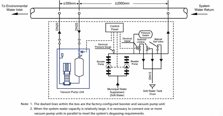
YONGFAN water make-up and vacuum degassing installation diagram
Hydraulic Reference Point

Why Make-Up Flow Is Not Expansion Capacity

Per ASHRAE Hydronic Heating and Cooling, make-up pumps replace lost water against injection point pressure, while expansion vessels absorb thermal volume expansion.

Make-Up Flow vs. Expansion Capacity

Make-up flow specifies how fast lost water is replaced. Expansion volume depends on total loop water content, temperature rise, and allowable pressure swing.

Impact: Relief valve dumping on thermal rise

Sizing on Floor Area Alone

Two buildings with identical floor area can have wildly different water content due to pipe sizing, terminal types, and riser distribution.

Impact: Undersized stabilization skid

Make-Up Head Calculation Error

Make-up pumps do not lift the full building water column in a closed loop. They inject water against the pressure at the connection point plus local friction.

Impact: Incorrect pump selection & motor overload

A vs. B Configuration Mismatch

JFWP-A uses compact controlled-discharge. JFWP-B includes an atmospheric expansion vessel to retain and recover bulk expansion water.

Impact: Unrecovered water or plant-room footprint overrun

Five Decision Inputs for Exact JFWP Sizing

Verified against GB 50736, GB 50019 & JG/T 408 HVAC standards.

01 Total Closed-Loop Water Capacity (m³)
02 Rated Make-Up Flow (m³/h)
03 Pressure Class (0.6 / 1.0 / 1.6 MPa)
04 A (Compact) vs. B (Tank) Strategy
02 / Model Portfolio

JFWP Series Model Table: 8 Standard Skid Sizes

System water capacity sets the JFWP model, while operating pressure sets the pump head and pressure-vessel class.
Model Max. System Water Capacity Rated Make-Up Flow Reference Heating Area Reference Cooling Area Working Pressure Classes
JFWP-1 48 m³ 2.4 m³/h 10,000 m² 5,000 m² 0.6 / 1.0 / 1.6 MPa
JFWP-2 100 m³ 4.8 m³/h 20,000 m² 10,000 m² 0.6 / 1.0 / 1.6 MPa
JFWP-3 160 m³ 7.2 m³/h 40,000 m² 18,000 m² 0.6 / 1.0 / 1.6 MPa
JFWP-4 200 m³ 9.6 m³/h 60,000 m² 25,000 m² 0.6 / 1.0 / 1.6 MPa
JFWP-5 230 m³ 11.0 m³/h 80,000 m² 35,000 m² 0.6 / 1.0 / 1.6 MPa
JFWP-6 260 m³ 16.0 m³/h 120,000 m² 48,000 m² 0.6 / 1.0 / 1.6 MPa
JFWP-7 360 m³ 20.0 m³/h 150,000 m² 65,000 m² 0.6 / 1.0 / 1.6 MPa
JFWP-8 480 m³ 24.0 m³/h 200,000 m² 85,000 m² 0.6 / 1.0 / 1.6 MPa

*Make-up pump heads selectable across 11 standard steps: 24, 32, 40, 48, 56, 64, 72, 80, 88, 96, 104, and 112 m (Motor power 0.37 to 15 kW).

03 / Architecture Comparison

JFWP-A vs. JFWP-B: Handling Expansion Water

Choose JFWP-A for compact plant-room footprints, or JFWP-B when retaining and recovering bulk expansion water is required.
Configuration A · Compact Skid

JFWP-A: Compact Controlled-Discharge

Uses a compact bladder vessel for pressure buffering. When system pressure exceeds upper limits on thermal expansion, overpressure relief discharges through a safety valve and tundish to drain. Best for reliable make-up sources and moderate temperature swings.

Footprint Span: 1600×1500×800 mm (JFWP-1A, 850 kg) to 2000×1800×1000 mm (JFWP-8A, 3500 kg). Connections DN50–DN100.
Configuration B · Expansion Storage

JFWP-B: Atmospheric Expansion Vessel

Adds an integrated atmospheric expansion vessel. Overpressure discharge is received into the tank and automatically pumped back into the closed loop when pressure drops. Essential for larger temperature swings or intermittent make-up supply.

Footprint Span: 1800×1300×1300 mm (JFWP-1B, 1250 kg) to 2400×1700×1500 mm (JFWP-8B, 3800 kg). Dedicated DN25 overflow/drain.
04 / Procurement Protocol

Information Required for Accurate JFWP Sizing

Do not select JFWP from floor area alone. Provide system water volume, temperature range, injection pressure, and A/B preference.
STEP 01

System Water Volume

Total closed-loop water capacity (m³) across piping, terminals, and boilers.

STEP 02

Operating Temperatures

Cold fill temperature and maximum design supply water temperature (°C).

STEP 03

Pressure & Make-Up Head

Working pressure class (0.6/1.0/1.6 MPa) and pump head at the connection point.

STEP 04

A vs. B Architecture

Compact controlled discharge (A) or atmospheric expansion retention (B).

Engineering Handoff

Submit System Parameters for JFWP Skid Sizing

YONGFAN engineers will calculate expansion volume, verify make-up pump head, and provide GA layout drawings.

Total Closed-Loop Volume (48–480 m³)
Make-Up Pump Head (24–112 m)
Pressure Class: 0.6 / 1.0 / 1.6 MPa
Configuration: JFWP-A or JFWP-B
Water Temperature: 5–80 °C (or >80 °C)
BMS Protocol: Modbus RTU / BACnet
05 / Manufacturing Quality

Skid Assembly & Hydrostatic Loop Verification

Every JFWP skid undergoes 1.5× design pressure hydrostatic testing and 24-hour operational testing before sign-off.
Pumps QA

Dual Stainless Pumps

Two stainless-steel multistage pumps per skid with automated duty/standby rotation and parallel cut-in logic.

Pressure QA

1.5× Hydrostatic Test

Complete wetted skid circuit tested at 1.5× design pressure for 30 minutes with zero allowable pressure drop.

Control QA

24-Hour Soak Run

Operational sequence verified: setpoint cycling, low-water cutoff, relief discharge, and PLC alarm logging.

BMS QA

Modbus / BACnet

Factory-wired RS-485 Modbus RTU standard with BACnet MS/TP and IP gateway integration verified on test bench.

Lead Time: 15–25 working days standard; 25–35 working days for JFWP-B with custom pump trims. Trade Terms: EXW, FOB, CIF, CFR, and DDP export logistics supported.
06 / Engineering Knowledge

Pressure Stabilizing & Expansion Units FAQ

Direct engineering answers regarding JFWP capacities, A vs. B differences, pump heads, and vacuum degassing.

What is the JFWP capacity range?

The documented family covers 48–480 m³ of maximum closed-system water capacity with rated make-up flow from 2.4 to 24 m³/h across 8 sizes.

What is the difference between JFWP-A and JFWP-B?

JFWP-A is the compact arrangement with controlled overpressure discharge to drain. JFWP-B includes an atmospheric vessel to receive and return bulk expansion water.

How many make-up pumps are supplied?

Two pumps per skid, with automatic duty/standby rotation and parallel pump cut-in during large leakage events.

Does JFWP provide vacuum degassing?

No. JFWP includes automatic air venting. Vacuum degassing of dissolved gases belongs to YONGFAN’s separate JFDT Vacuum Degassing product family.

Can JFWP connect to a BMS?

Yes. RS-485 / Modbus RTU is standard. BACnet MS/TP and BACnet/IP gateways are available on request.

What is the standard make-up water temperature?

5–80 °C for the standard skid. Higher temperatures (90–95 °C) require upgraded EPDM bladders and pump mechanical seals.

07 / Application Boundaries

JFWP Engineering Boundaries

Key engineering rules for closed-loop hydronic expansion and stabilization.
Boundary 01 / Floor Area Sizing

Water Volume Governs

Do not select the skid only from floor area; calculate actual closed-loop water content.

Boundary 02 / Head Calculation

Injection Pressure

Do not calculate make-up head as circulation pump lift; calculate pressure at the injection point.

Boundary 03 / Expansion Storage

Choose B for Retention

Do not choose JFWP-A if the project requires retaining expansion water in an atmospheric reservoir.

Boundary 04 / Degassing Function

Venting vs. Degassing

Do not assume automatic air venting removes dissolved oxygen; specify JFDT for vacuum degassing.

08 / Engineering Handoff

Select the Right JFWP Pressure Stabilizing & Expansion Skid

Send your system water volume, design temperature range, and injection point pressure. YONGFAN application engineers will verify make-up flow, expansion volume, and provide complete submittal drawings.


Loop Volume: 48–480 m³ Make-Up Flow: 2.4–24 m³/h Pump Head: 24–112 m 0.6 / 1.0 / 1.6 MPa Classes JFWP-A (Compact) / JFWP-B (Tank) 1.5× Hydrostatic Tested
YONGFAN application engineers reviewing expansion skid drawings
Direct Application Engineering Support
Hydronic volume sizing, pump head verification & certified GA drawings.
