Electronic water treatment must match flow, hardness, temperature and pipe layout; wrong JFGP sizing can add pressure loss without addressing the water-quality problem.
YONGFAN JFGP Series provides inline physical descaling across 16 standardized sizes (DN15–DN600), operating on water hardness <700 mg/L as CaCO₃ and temperatures ≤95 °C with minimal head loss (≤1.5 m H₂O).
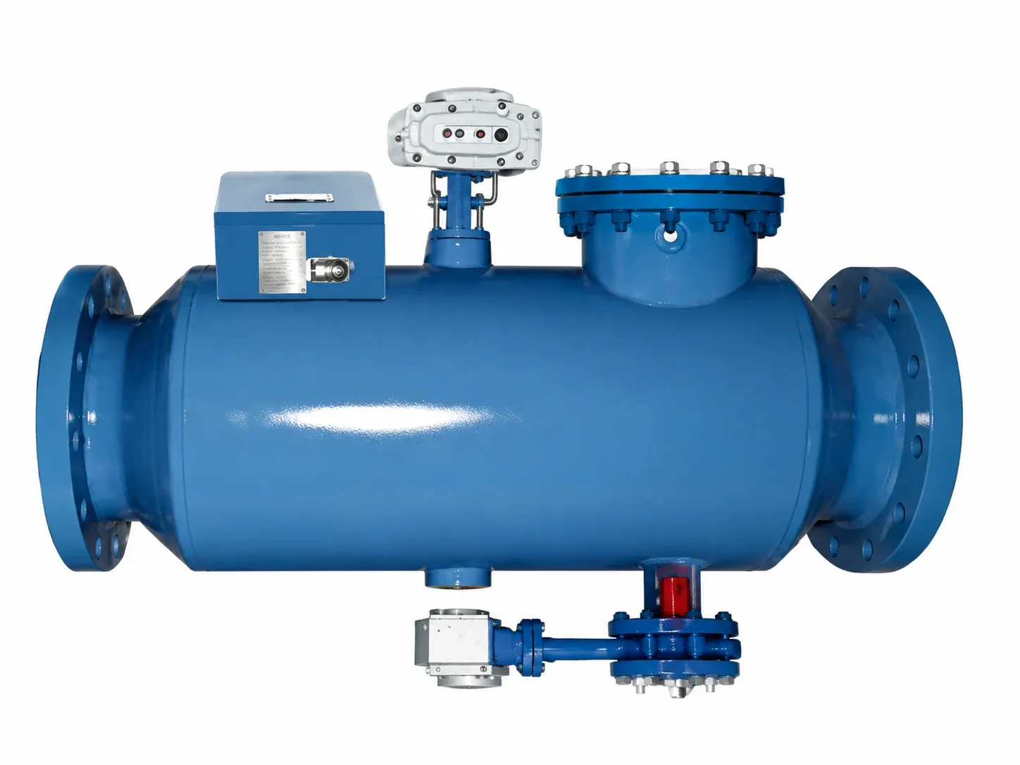
Ordering JFGP-100 just because the pipe is DN100 causes severe mis-sizing if peak system flow exceeds 80 m³/h or sits far below rated velocity.
Standard JFGP is limited to hardness <700 mg/L as CaCO₃. Water above 700 mg/L requires Induction Treatment (up to 2,000 mg/L) or RLC Softeners.
Standard JFGP is rated for water temperatures ≤95 °C. Higher-temperature heating loops exceed standard electrode insulation limits.
Physical conditioning does not remove dissolved calcium/magnesium. If process specifications require low residual hardness, specify RLC softeners.
| Model | Rated Flow (m³/h) | Power (W) | Body Length (mm) | Net Weight (kg) |
|---|---|---|---|---|
| JFGP-15 | 1 | 10 W | 540 | 9 kg |
| JFGP-25 | 4 | 30 W | 540 | 10 kg |
| JFGP-40 | 10 | 45 W | 600 | 12 kg |
| JFGP-50 | 25 | 50 W | 600 | 15 kg |
| JFGP-80 | 40 | 65 W | 600 | 32 kg |
| JFGP-100 | 80 | 80 W | 600 | 35 kg |
| JFGP-125 | 125 | 100 W | 800 | 44 kg |
| JFGP-150 | 150 | 100 W | 800 | 54 kg |
| JFGP-200 | 300 | 300 W | 800 | 70 kg |
| JFGP-250 | 400 | 300 W | 1,000 | 120 kg |
| JFGP-300 | 600 | 300 W | 1,000 | 140 kg |
| JFGP-350 | 900 | 400 W | 1,000 | 160 kg |
| JFGP-400 | 1,250 | 400 W | 1,200 | 200 kg |
| JFGP-450 | 1,500 | 400 W | 1,200 | 230 kg |
| JFGP-500 | 2,700 | 400 W | 1,200 | 250 kg |
| JFGP-600 | 2,000* | 500 W | 1,400 | 350 kg |
*Four physical installation forms available: straight-through, right-angle, same-side, and opposite-side to match existing plant-room pipe runs.
| Specification | Documented Value | Verification Requirement |
|---|---|---|
| Standard Sizes | 16 models, JFGP-15 to JFGP-600 | Match approved flange schedule (DN15–DN600) |
| Treatment Flow | 1 – 2,700 m³/h | Select from peak design flow, not daily average |
| Water Hardness | <700 mg/L as CaCO₃ | Submit laboratory water chemistry report |
| Water Temperature | ≤95 °C | Check maximum system upset temperature |
| Head Loss | ≤1.5 m H₂O (~15 kPa) | Confirm circulating pump residual head margin |
| Electrical Power | 220 V, 50 Hz · 10–500 W | Single-phase power connection at controller |
| Operating Frequency | Up to 12 MHz | GB 4824 industrial EMC compliance |
| Metallurgy | Q235-B std; SS304 / SS316L opt | Match fluid chloride and corrosion requirements |
| Cabinet Protection | IP54 indoor / IP65 outdoor opt | Specify outdoor weatherproof enclosure if exposed |
Peak water flow rate (m³/h) through the planned installation header.
Total hardness as CaCO₃ (<700 mg/L) and maximum temperature (≤95 °C).
Flange standard, nominal diameter (DN), and shell material (Carbon/SS316L).
Straight-through, right-angle, same-side, or opposite-side nozzle layout.
YONGFAN application engineers will verify flow velocity, confirm pressure drop, and provide certified submittal drawings.
Every electrode assembly undergoes 5,000 V dielectric testing to ensure complete electrical isolation from the steel shell.
High-frequency generators are individually tested on calibrated oscilloscopes to verify output waveform and power levels.
Every pressure-containing pipe body is tested at 1.5× design pressure to GB 150 pressure vessel standards.
Controllers housed in IP54 powder-coated cabinets (or optional IP65 weatherproof enclosures with UV coating).
The standard headline range spans 1–2,700 m³/h across 16 sizes (DN15–DN600).
The standard application boundary is <700 mg/L total hardness as CaCO₃.
No. JFGP is physical conditioning that prevents hard crystal bonding. Use Water Softeners (RLC) when measured chemical hardness removal is required.
Yes. JFGP is an inline flanged vessel. If the plant cannot stop, review Induction Water Treatment for non-invasive coil wrapping.
Standard JFGP is rated for water temperatures ≤95 °C.
Yes. An optional RS-485 Modbus RTU interface provides status, output power, runtime, and alarm data.
Do not apply standard JFGP where water hardness exceeds 700 mg/L CaCO₃ without upgrading to induction or softeners.
Do not apply standard units above 95 °C without engineering approval for specialized high-temperature electrode seals.
JFGP does not remove suspended rust or debris; combine with SGV-PW or side-stream filters for particulate cleanup.
Do not specify JFGP solely from pipe DN; match the unit to actual peak flow (70–90% of rated capacity).
Send your peak flow rate, pipe size, water hardness, and temperature. YONGFAN application engineers will verify sizing, recommend body metallurgy, and provide dimensioned submittal drawings.


