YONGFAN HVAC - Premium Header
Engineered HVAC & Industrial Air Systems
YONGFAN HVACYOFAN HVAC Home
Cleanroom Terminal Equipment | YONGFAN
Cleanroom Ceiling Systems (ISO 14644-1 · ISO 14644-3 · 500–3,000 m³/h)

Cleanroom Terminal Equipment: Airflow Balancing & Ceiling Coordination

A mismatched terminal can leave a cleanroom short of airflow, difficult to balance, or unable to pass installed leakage and particle-control tests.

Compare YONGFAN GFK passive HEPA diffuser boxes (500–3,000 m³/h), GCFK ultra-thin shallow-ceiling terminals (150 mm depth), and FFU fan filter units (900 m³/h, ≤54 dB(A)) by pressure source, ceiling depth, and HEPA efficiency.

3 Core Routes GFK (Passive) · GCFK · FFU (Fan)
Airflow Range 500 – 3,000 m³/h per Unit
Ceiling Depths 150 mm (GCFK) · Standard Diffuser
Pressure Strategy Central Static vs. Distributed Fan
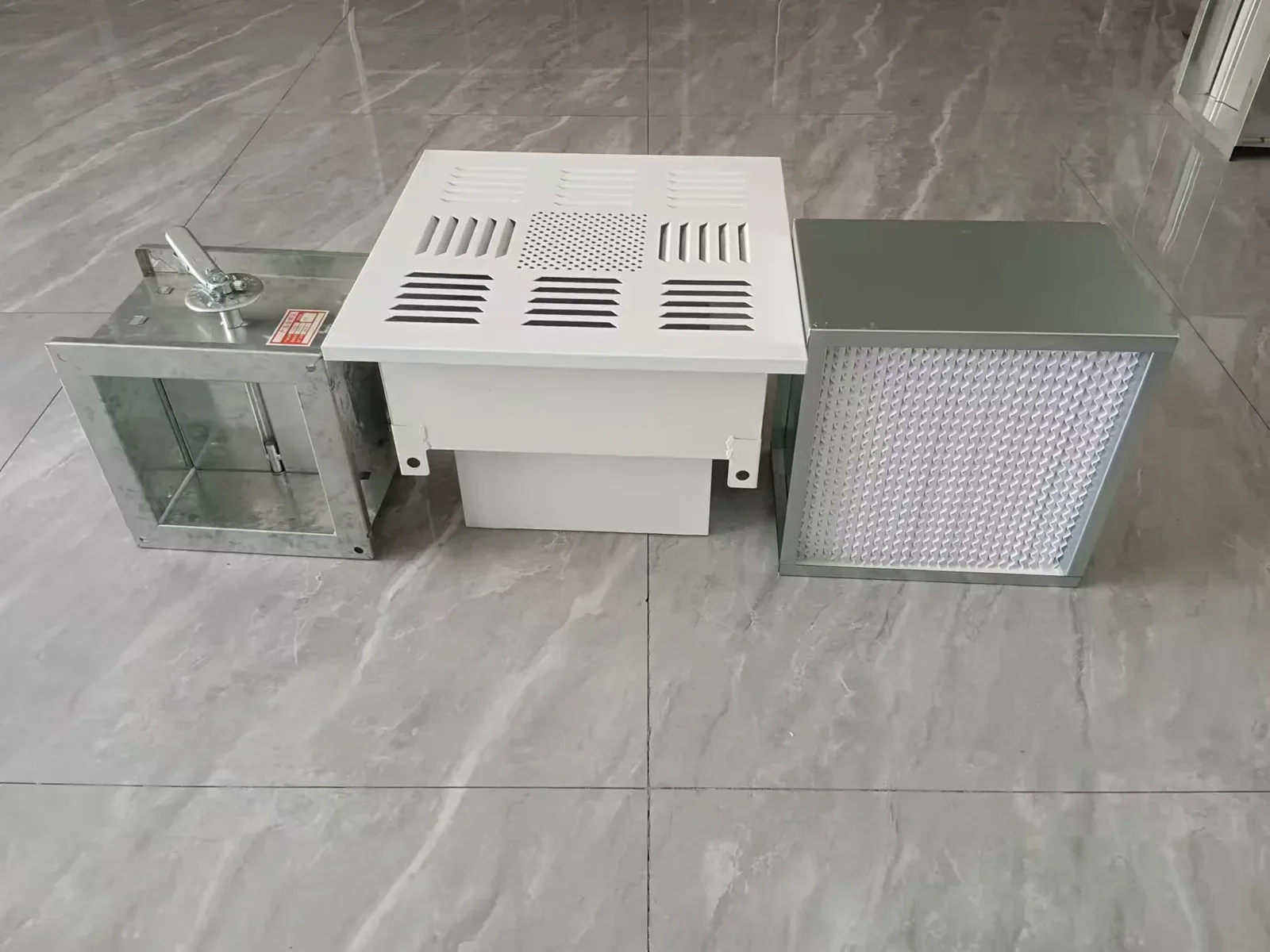
YONGFAN cleanroom HEPA supply air terminal
Cleanroom Ceiling Integration ISO 14644-1 Airflow Balancing, Shallow Void Geometry & Zero-Bypass Sealing
01 / Failure Mechanisms

Cleanroom Terminal Failures Often Start at the Ceiling

Commissioning starts: one group of terminals delivers less air than scheduled; another passes airflow but shows bypass leakage around the housing seal; a third creates excessive fan motor noise in clean zones.
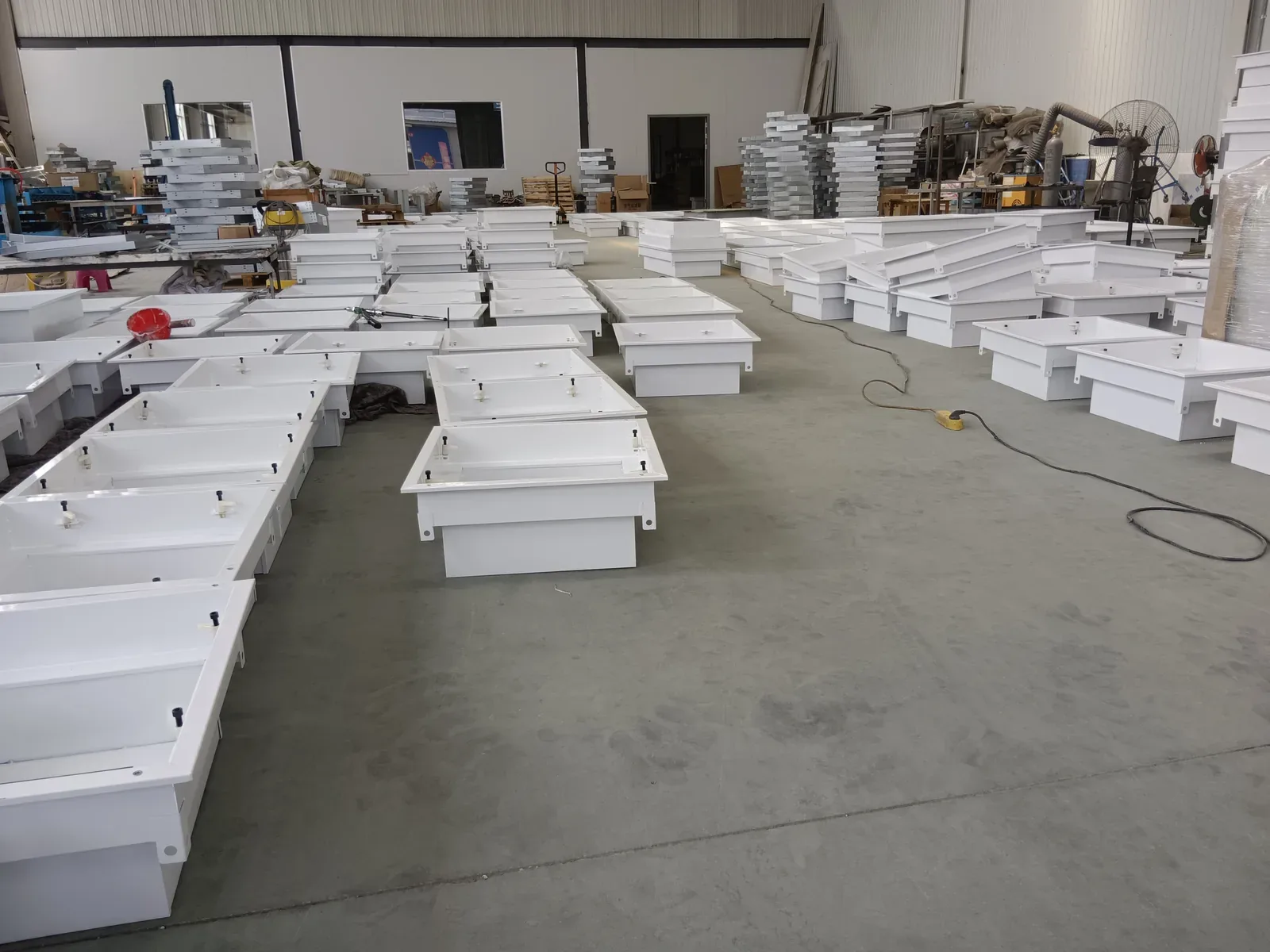
YONGFAN cleanroom terminal equipment production batch
Installed Boundary

Why Terminal Selection Controls Validation

ISO 14644-1 particle limits and ISO 14644-3 test methods make the consequences of mismatched terminal pressure, depth, and sealing immediately visible.

Central Static Pressure Starvation

Passive diffusers (GFK/GCFK) rely entirely on central duct static head. If duct losses exceed fan margins, terminals deliver sub-design airflow.

Impact: Inadequate room air change rate (ACH)

Ceiling Void Spatial Collisions

Forcing standard deep diffuser boxes into shallow plenum voids causes sharp duct bends, inaccessible filter clamps, or installation blockages.

Impact: Duct friction spikes & maintenance obstruction

Terminal Frame Bypass Leakage

Poorly clamped filter seats or unaligned dry-gasket seals leak raw air directly into the sterile suite, failing installed aerosol scan qualification.

Impact: Cleanroom particle count failure

Unbudgeted FFU Noise & Power Load

Deploying motorized FFUs across large grid areas without planning acoustic limits (≤54 dB(A)) or single-phase 220V power leads to occupied zone complaints.

Impact: Excessive room NC rating & electrical overload

Terminal Selection Resolves Five Structural Boundaries

Successful cleanroom ceilings align unit airflow, central vs. fan-powered pressure, plenum depth, duct orientation, and HEPA sealing.

01 Terminal Airflow (500 to 3,000 m³/h)
02 Pressure Source (Passive AHU vs FFU Fan)
03 Ceiling Void Depth (150 mm GCFK vs GFK)
04 Duct Supply Direction (Side vs Top Entry)
02 / Technical Parameters

Specifications Controlling Installed Cleanroom Performance

The engineering boundaries that distinguish passive diffuser boxes from ultra-thin units and motorized fan filter units.
Specification 01 / Capacity

Airflow per Terminal

YONGFAN’s passive GFK family spans 500 to 3,000 m³/h for large module coverage. GCFK covers 600, 900, and 1,200 m³/h. FFU modules are rated at 900 m³/h for distributed ceiling grids.

Specification 02 / Aerodynamic

Pressure & Resistance Source

GFK and GCFK are passive terminals requiring upstream AHU fan static pressure (GCFK ≤120 Pa initial ΔP). FFU integrates an internal centrifugal fan, generating its own terminal static pressure.

Specification 03 / Mechanical

Terminal Depth & Duct Entry

GCFK maintains a strict 150 mm overall depth for restricted ceiling voids with round duct connections. GFK utilizes 69/80/150/220 mm filter depths with side- or top-supply rectangular/round spigots.

Cleanroom Terminal Performance Architecture

Published performance boundaries from YONGFAN cleanroom engineering tables.

ISO 14644-1 · ISO 29463 Basis
GFK Diffuser Box
500–3,000 m³/h
Passive central duct · Side/Top entry · 69–220 mm filters
GCFK Ultra-Thin
150 mm Depth
600/900/1,200 m³/h · ≤120 Pa · ≥99.99% MPPS · Round duct
FFU Fan Filter Unit
900 m³/h · Fan-Powered
≤54 dB(A) · 180 VA · AC 220V 1φ · Distributed clean air
03 / Product Lineup

Cleanroom Terminals by Pressure Source & Ceiling Depth

YONGFAN manufactures three distinct terminal routes: full-capacity passive diffuser boxes, ultra-thin low-profile units, and motorized fan filter units.
Family 01 · GFK Series 500–3,000 m³/h · Central AHU Duct

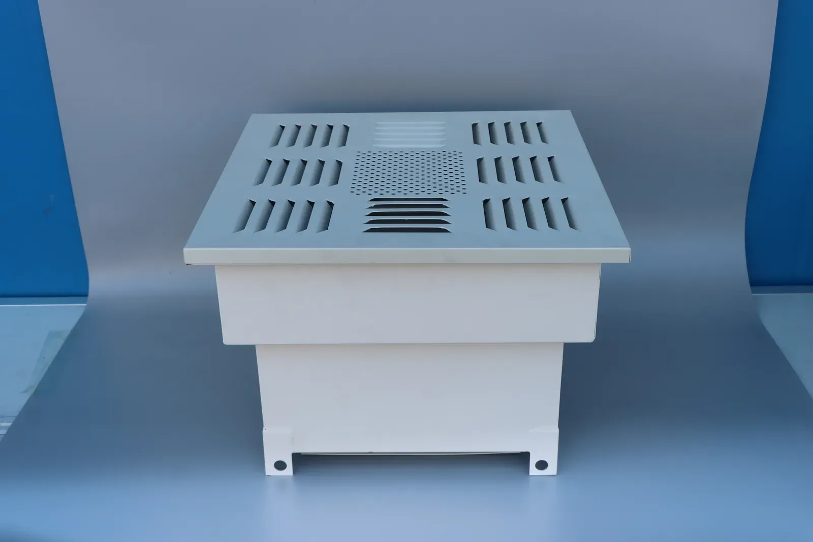
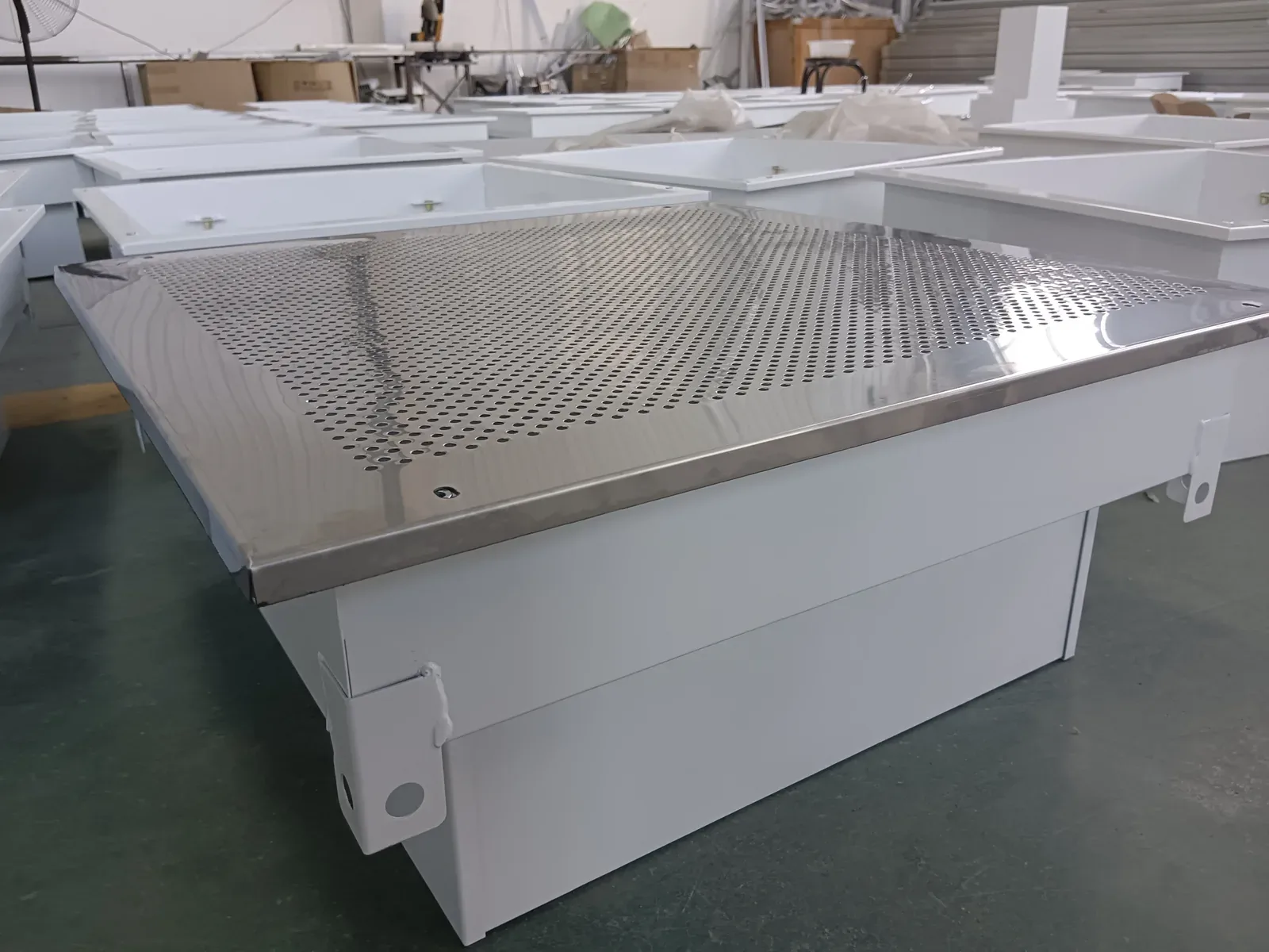
GFK HEPA Supply-Air Diffuser Box

The GFK HEPA Supply-Air Diffuser Box is the broadest passive terminal family in YONGFAN’s cleanroom range. It is designed for applications where central AHUs provide conditioned air and static pressure.

Covering 500 to 3,000 m³/h, GFK features cold-rolled steel bodies with epoxy powder-coating (galvanized steel, stainless steel -S, and aluzinc -AZ options available). Available with-separator (side/top supply, GFK320–GFK1260) and without-separator (top-supply, GFK320F–GFK1260F) across filter depths of 69, 80, 150, and 220 mm.

Airflow Capacity
500 – 3,000 m³/h per Unit
Supply Orientation
Side-Entry & Top-Entry (Model D)
Filter Depths Supported
69 mm, 80 mm, 150 mm, 220 mm
Body Materials
Powder-Coated Steel, SS (-S), Aluzinc (-AZ)
System Duct Balancing: Because GFK relies on central fan static pressure, branch duct sizing, VAV/manual balancing dampers, and filter resistance must be coordinated as an integrated airside network.
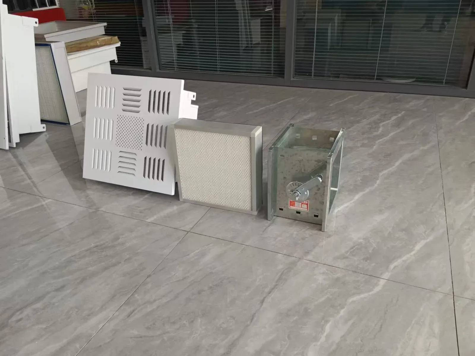
YONGFAN HEPA terminal diffuser assembly
GFK HEPA Supply-Air Diffuser Box
Key Capabilities:
  • Widest capacity coverage up to 3,000 m³/h
  • Side-spigot for tight vertical ceiling clearances
  • Diffuser plates: Perforated, Swirl, or 4-Way
  • Integrates with GCDZ high-efficiency filters
Family 02 · GCFK Series 150 mm Ultra-Thin · Negative-Pressure Seal

GCFK Ultra-Thin HEPA Diffuser

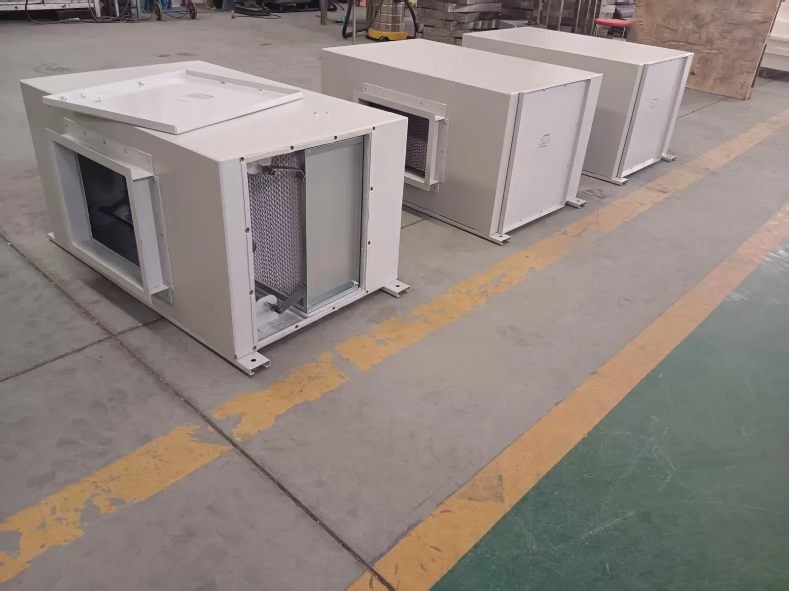
The GCFK Ultra-Thin HEPA Diffuser solves shallow ceiling plenum conflicts where a conventional diffuser box cannot fit. All standard models feature a uniform, ultra-low profile of 150 mm overall depth.

The published range includes GCFK-6 (610×610×150 mm, 600 m³/h), GCFK-9 (915×610×150 mm, 900 m³/h), and GCFK-12 (1,220×610×150 mm, 1,200 m³/h). Published with ≤120 Pa initial resistance, ≥99.99% efficiency at MPPS, round flexible duct connection spigots, and negative-pressure sealing.

Overall Depth
150 mm (Uniform across all 3 models)
Standard Ratings
600 m³/h (GCFK-6) · 900 m³/h (GCFK-9) · 1,200 m³/h (GCFK-12)
Initial ΔP & MPPS
≤120 Pa · ≥99.99% MPPS (ISO 29463-1)
Duct Connection
Top Round Spigot for Flexible / Spiral Duct
Ceiling Capacity Limit: If an individual ceiling location requires >1,200 m³/h, evaluate standard GFK or increase terminal quantity rather than forcing GCFK beyond its published duty.
YONGFAN horizontal exhaust HEPA filter housing
GCFK 150 mm Ultra-Thin Terminal
Shallow Void Benefits:
  • Fits plenum spaces under 250 mm total clearance
  • Direct round duct drop without rectangular transitions
  • Aluminium body + galvanized top plate (80 °C / 80% RH)
  • Negative-pressure leak prevention design
Family 03 · FFU Series 900 m³/h · Distributed Fan-Powered

FFU Fan Filter Unit

The FFU Fan Filter Unit integrates an internal backward-curved centrifugal fan directly with a HEPA terminal module. It shifts pressure generation from central AHUs directly to the cleanroom ceiling grid.

Documented for the 901/910 family with rated performance of 900 m³/h, acoustic level of ≤54 dB(A), electrical input of 180 VA (AC 220V ±10%, single-phase, 50 Hz ±2 Hz), and HEPA efficiency of ≥99.99% at 0.3 µm. Features low-vibration construction, separable fan/filter assembly for easy maintenance, and multi-step speed control.

Rated Airflow
900 m³/h (Standard 901/910 Module)
Acoustic Level
≤54 dB(A) (Low-noise aerodynamic shroud)
Power & Input
180 VA · AC 220V ±10%, 1-Phase, 50 Hz
HEPA Efficiency
≥99.99% @ 0.3 µm (Separable Module)
Electrical & Acoustic Budget: FFUs introduce electrical motors above ceilings. Include power distribution, speed-control networking, and acoustic summation whenever designing multi-unit grids.
YONGFAN cleanroom HEPA terminal set
FFU Motorized Fan Filter Unit
Distributed Grid Advantages:
  • Independent local airflow control per ceiling cell
  • Eliminates large branch ductwork networks
  • Separable fan and HEPA filter for rapid replacement
  • Multi-step speed regulation for pressure balancing
04 / Selection Matrix

Cleanroom Terminal Equipment Comparison & Routing

Cross-reference YONGFAN cleanroom terminal families by pressure architecture, airflow boundaries, and key project confirmation inputs.
Product Family What It Solves Range Boundary (YONGFAN Data) First Input to Confirm Specification Action
GFK Diffuser Box 500–3,000 m³/h
Passive HEPA terminal supplied by central AHU duct pressure over a broad airflow range
500–3,000 m³/h · Side/Top supply · 69/80/150/220 mm filters
Available central static pressure and supply direction Configure GFK
GCFK Ultra-Thin 150 mm Depth
Passive HEPA terminal where ceiling void height is strictly restricted
600/900/1,200 m³/h · 150 mm depth · ≤120 Pa · ≥99.99% MPPS
Maximum clear ceiling void depth Configure GCFK
FFU Fan Filter Unit Fan-Powered
Fan-powered terminal for distributed cleanroom air supply without central branch ducts
900 m³/h · ≤54 dB(A) · 180 VA · AC 220V 1φ · ≥99.99% @ 0.3 µm
Central-pressure system vs. local fan-powered grid Configure FFU
Criterion 01

Pressure Architecture

If central fan static pressure is available, choose GFK or GCFK. If distributed ceiling fan power is required, choose FFU.

Criterion 02

Ceiling Void Clearance

If clear depth is under 250 mm, 150 mm GCFK solves installation. With adequate height, GFK supports high airflow up to 3,000 m³/h.

Criterion 03

Duct Approach Direction

GFK with-separator supports side-entry or top-entry spigots. GCFK utilizes top round spigots for flexible duct connections.

Criterion 04

Acoustic & Power Budget

FFUs require room-level acoustic budgeting (≤54 dB(A)) and single-phase 220V power supply at each ceiling location.

05 / Procurement Protocol

Information Required for a Cleanroom Terminal Quote

A cleanroom terminal inquiry requires room air strategy, plenum void depth, and pressure source before freezing the reflected ceiling plan.
STEP 01

Room Cleanliness & Airflow

State ISO cleanroom class (ISO 5–8), total supply airflow, and target airflow per ceiling terminal (m³/h).

STEP 02

Pressure & Architecture

Confirm whether central AHU duct pressure is available (GFK/GCFK) or motorized ceiling fan power (FFU) is specified.

STEP 03

Ceiling Void & Duct Layout

Provide clear ceiling void height, duct connection size, and approach direction (side-entry vs top-entry drop).

STEP 04

Filter Class & Sealing

Specify HEPA class and test basis (≥99.99% MPPS vs 0.3 µm), diffuser faceplate style, and body material.

Engineering Handoff

10 Parameters for Accurate Cleanroom Terminal Quotes

Send your ceiling plans and air schedules. YONGFAN application engineers will verify pressure drops, void clearances, and acoustic performance.

1. Room Cleanliness ISO Class (ISO 14644-1)
2. Design Airflow per Terminal (m³/h)
3. Pressure Strategy: Central AHU vs. FFU
4. Maximum Available Ceiling Void Depth
5. Duct Approach: Side-Entry vs Top-Entry
6. HEPA Test Basis: MPPS vs 0.3 µm Aerosol
7. Housing Material: Cold-Rolled / SS / Aluzinc
8. Power Supply for FFU (AC 220V 1-Phase)
9. Diffuser Faceplate Type (Perforated / Swirl)
10. Installed Leakage Scan Test Protocol
06 / Manufacturing Verification

YONGFAN Terminal Equipment Production Controls

Dedicated in-house manufacturing combining precision sheet metal laser cutting, automated powder coating, mini-pleat HEPA assembly, and aerodynamic fan testing.
Precision Sheet Metal

CNC Laser & Bending

Tight tolerance CNC cutting, corner welding, and continuous electrostatic powder-coating guarantee airtight terminal box geometry and corrosion resistance.

Individual Scan Testing

HEPA Scan Verification

Integrated HEPA filter elements are 100% scan-tested for pinhole leakage and seal integrity using calibrated particle counters prior to terminal packing.

Acoustic & Vibration

FFU Motor Balance

Every FFU fan assembly is dynamically balanced to ensure vibration isolation, low operating noise (≤54 dB(A)), and steady long-term aerodynamic delivery.

Traceability

Factory Submittals

Each terminal is labelled with model code, rated airflow, electrical parameters, filter batch, and dimensional QA stamps for project validation.

7–15 Days Fast Dispatch: Standard catalog configurations for GFK, GCFK, and FFU modules dispatched rapidly for export projects. Project Engineering: Non-standard diffuser dimensions, stainless steel housing construction (-S), and custom spigots engineered to order.
07 / Engineering Knowledge

Cleanroom Terminal Equipment Frequently Asked Questions

Technical answers to key selection questions regarding passive vs. powered terminals, shallow ceiling clearances, and duct connections.

Which YONGFAN cleanroom terminal uses central fan pressure?

Both GFK HEPA Diffuser Boxes and GCFK Ultra-Thin Diffusers are passive routes. GFK covers 500–3,000 m³/h, while GCFK provides a shallow 150 mm profile for 600–1,200 m³/h duties.

Which terminal should I use when the ceiling void is shallow?

The GCFK Ultra-Thin HEPA Diffuser is the dedicated solution because all standard models feature a uniform 150 mm overall depth.

Which YONGFAN terminal includes its own fan?

The FFU Fan Filter Unit integrates an internal centrifugal fan with the HEPA terminal, delivering 900 m³/h at ≤54 dB(A) and 180 VA power draw.

Which terminal supports side-entry ductwork?

The GFK with-separator family is documented with both side- and top-supply arrangements, allowing horizontal duct connections in tight vertical plenums.

Which YONGFAN terminal covers the largest airflow per unit?

The GFK HEPA Diffuser Box provides the widest capacity coverage in the range, delivering up to 3,000 m³/h from a single ceiling module.

Which terminal should I choose for a 900 m³/h cleanroom module?

Three routes intersect 900 m³/h: GCFK-9 (passive ultra-thin 150 mm), FFU 901/910 (motorized local fan), or a compatible GFK passive box.

Are GCFK and FFU efficiency values directly comparable?

No. GCFK is published at ≥99.99% MPPS (ISO 29463), while FFU is published at ≥99.99% at 0.3 µm. Always verify against project test specifications.

Can GFK replace an FFU without changing the air system?

Not usually. GFK depends on central duct static pressure, whereas FFUs generate airflow locally. Switching architectures changes duct pressure, electrical distribution, and controls.

08 / Application Boundaries

Cleanroom Terminals Are Not Standalone Filters or AHUs

Understanding product scope boundaries ensures accurate specifications and prevents system-level misapplications.
Boundary 01 / Replacement Filter

Not Just Filter Elements

If you only need a replacement filter element for an existing housing, specify GCDZ HEPA filters rather than complete terminal assemblies.

Boundary 02 / Thermal Conditioning

Not Complete AHUs

GFK, GCFK, and FFUs do not provide cooling, heating, or humidity control. Thermal conditioning remains the responsibility of upstream air-handling systems.

Boundary 03 / Molecular Gas

Do Not Remove VOCs

HEPA terminals remove airborne particulates. If the application involves toxic, corrosive, or odor-causing gases, specify activated-carbon chemical filtration.

Boundary 04 / Cleanroom Class

Room-Level System Performance

Cleanroom ISO classification cannot be guaranteed by terminal selection alone; envelope leakage, pressurization, airflow patterns, and commissioning govern final room performance.

09 / Engineering Handoff

Select the Right Cleanroom Terminal for Your Ceiling Grid

Send your cleanroom class, target airflow per location, ceiling plenum height, and pressure preference — YONGFAN cleanroom engineers will verify dimensional fit, static pressure, and diffuser patterns.

Terminal Airflow (500–3,000 m³/h) Plenum Void Depth (150 mm vs Deep) Pressure: Central AHU vs. FFU Duct: Side-Entry vs. Top-Spigot HEPA Class: ≥99.99% MPPS Housing: Powder-Coated Steel / SS
YONGFAN side-access HEPA terminal components
Cleanroom Application Engineering
Terminal pressure calculations, ceiling void coordination & CAD layout verification.