
YONGFAN HVAC - Premium Header
Engineered HVAC & Industrial Air Systems
YONGFAN HVACYOFAN HVAC Home
Menu
Hydronic Plant Room Systems | YONGFAN
Plant Room Engineering · Pressure Maintenance, Water Supply, Distribution & Balancing · PN0.6 to PN2.5 MPa

Hydronic Plant Room Systems: Closed-Loop Pressure, Pumping & Hydraulic Distribution

A hydronic plant room works only when pressure maintenance, pumping, distribution, balancing and control are assigned to the right equipment instead of being treated as one generic water-supply package.

Coordinate YONGFAN JFDY bladder pressure vessels (0.20–8.53 m³), JFWP packaged closed-loop expansion skids (48–480 m³ water capacity), JFHB constant-pressure VFD boosters (8–5,500 m³/h), JFWZ direct municipal non-negative-pressure units (8–280 m³/h), custom water distributors/collectors (DN50–DN500 main), balancing valves, 100X–900X hydraulic valves, and JFLN steam condensate recovery.

JFWP Expansion 48–480 m³ Closed Volume · Skid
JFDY Bladder Tank 0.20–8.53 m³ · Butyl Bladder
JFHB VFD Booster 8–5,500 m³/h · 20–250 m Head
JFWZ Non-Negative 8–280 m³/h · Direct Mains
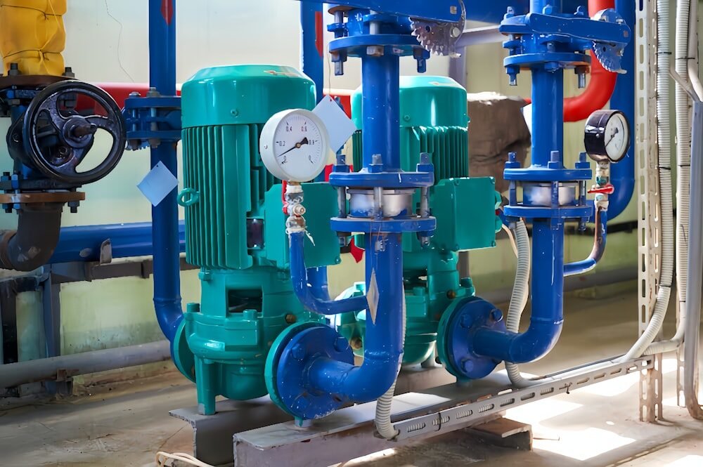
Central hydronic plant room with packaged pressure expansion skids, distribution headers, pumps, and balancing valves
Hydronic Plant Room Systems JFDY Bladder Tanks · JFWP Expansion Skids · JFHB VFD Boosters · JFWZ Non-Negative · Manifolds · Valves
01 / Hydraulic Boundary Analysis

Plant-Room Instability Often Starts With The Wrong Equipment Boundary

A closed hydronic loop recirculates the same water and requires thermal expansion absorption; domestic water boosting delivers fresh water under variable demand.
Hydronic expansion vessels, pressure transmitters, VFD pump skids, and distribution manifolds in central plant
Hydronic Equipment Boundaries

Closed-Loop Expansion (JFWP/JFDY) vs Constant-Pressure Boosting (JFHB/JFWZ)

Do not substitute domestic boosters for closed-loop expansion units; size pressure maintenance before pump control.

Domestic Booster Misapplied to Closed Loops

Installing a domestic booster pump on a closed chilled-water loop fails to accommodate thermal expansion, causing pressure relief dumping.

Impact: Daily water loss, constant air ingestion & corrosion

Direct Mains Boosting Without Back-Siphon Protection

Connecting standard booster pumps directly to municipal mains without non-negative-pressure controls violates municipal water codes.

Impact: Municipal main depressurization & regulatory shutdown

Unbalanced Distribution Manifolds

Fabricating distribution manifolds without branch balancing valves leaves index circuits starved while near circuits overflow.

Impact: Severe building temperature imbalance & chiller low ΔT

Misusing 800X Bypass for Branch Balancing

Installing 800X differential-pressure bypass valves on individual branch coils instead of central chiller decoupling headers.

Impact: Short-circuiting bypass flow & wasted pump energy

The Four Pillars of Hydronic Plant Room Design

Closed-loop pressure maintenance, constant-pressure boosting, manifold distribution, and hydraulic balancing.

01 / Closed-Loop Pressure JFDY bladder vessels & JFWP skids absorb thermal expansion and stabilize pressure
02 / Constant-Pressure Supply JFHB boosters (break tank) & JFWZ non-negative units (direct municipal mains)
03 / Circuit Distribution Custom water distributors & collectors organize multi-zone supply and return
04 / Balancing & Control DRV/BYF balancing valves, 100X–900X pilot valves & JFLN condensate recovery
02 / Portfolio Showcase

Hydronic Plant Room Product Families

Detailed engineering review of YONGFAN’s pressure-maintenance vessels, expansion skids, booster systems, and manifolds.
01 · JFDY Vessel Bladder Pressure Buffer · 0.20–8.53 m³

JFDY Constant-Pressure Water Make-Up Unit

Bladder-type pneumatic pressure vessel for closed-loop pressure stabilization and volume buffering (0.20–8.53 m³ total tank volume, 0.06–3.10 m³ effective regulating volume, PN 0.6/1.0/1.6 MPa, Ø400–Ø2000 mm, ≤80 °C water). Replaceable butyl-rubber bladder with dry nitrogen pre-charge.


Total Tank Volume
0.20 to 8.53 m³ Vessel Range
Regulating Volume
0.06 to 3.10 m³ Effective Volume
Working Pressure
0.6 / 1.0 / 1.6 MPa Ratings
Bladder Material
Replaceable Butyl Rubber + N2 Pre-Charge
Primary Applications

Closed HVAC chilled/hot water loops, district heating expansion buffering, and pressure stabilization.

02 · JFWP Expansion Packaged Expansion Skid · 48–480 m³ Water Capacity

JFWP Pressure Stabilizing & Expansion Unit

Factory-assembled closed-loop pressurization and expansion skid (heating area 10,000–200,000 m², cooling area 5,000–85,000 m², system water capacity 48–480 m³, make-up flow 2.4–24 m³/h, head 24–112 m, 0.6/1.0/1.6 MPa). JFWP-A is compact without atmospheric tank; JFWP-B includes atmospheric expansion vessel.

Water Capacity
48 to 480 m³ System Volume Coverage
Make-Up Flow
2.4 to 24 m³/h Automated Flow
Pump Head Range
24 to 112 m Head Capability
Skid Configurations
JFWP-A (Compact) & JFWP-B (Atmospheric Tank)
Primary Applications

Central HVAC chilled-water loops, commercial heating plants, boiler systems, and district cooling stations.

03 · JFHB VFD Booster VFD Constant-Pressure Booster · 8–5,500 m³/h

JFHB Fully Automatic Constant-Pressure VFD Water Supply

Variable-frequency booster pumping system for water supply from break tanks or positive-pressure sources (8–5,500 m³/h flow, 20–250 m head, 0.55–315 kW, regulation accuracy ≤0.01 MPa, PN 0.6/1.0/1.6 MPa). Automatically adjusts pump speed and staged staging to maintain constant network pressure.

Flow Capacity
8 to 5,500 m³/h Wide Flow Range
Head Envelope
20 to 250 m Pumping Head
Pressure Accuracy
≤0.01 MPa High-Precision Regulation
Suction Source
Break Tank / Storage Tank / Positive Feed
Primary Applications

High-rise domestic water supply, commercial building booster stations, industrial process water, and campus water networks.

04 · JFWZ Non-Negative Direct Municipal Mains Boosting · 8–280 m³/h

JFWZ Non-Negative-Pressure Water Supply Equipment

Connects directly to municipal water mains without requiring an atmospheric break tank (8–280 m³/h standard, 20–250 m head, 0.37–280 kW, ≤0.01 MPa accuracy, CJ/T 265 standard). Utilizes available municipal residual pressure while actively preventing negative pressure on the municipal main.

Flow Range
8 to 280 m³/h Direct Mains Range
Head Envelope
20 to 250 m Delivery Head
Energy Saving
Utilizes Existing Municipal Residual Head
Standard Compliance
CJ/T 265 Non-Negative Pressure Equipment
Primary Applications

Direct-mains commercial building booster stations, residential estates, and municipal pipe network boosting.

05 · Manifolds Custom Water Distributors & Collectors · To 2.0 MPa

Water Distributors & Collectors (Manifolds)

Custom-fabricated headers that divide supply mains and merge return circuits (working pressure to 2.0 MPa, <100 °C, carbon steel or stainless steel). Features 2–12+ branches (DN15–DN300), main diameters DN50–DN500, custom branch spacing, instrument tapping ports, and 1.5× hydrostatic testing.

Main Diameters
DN50 to DN500 Custom Manifolds
Branch Connections
2 to 12+ Branches (DN15 to DN300)
Pressure Ratings
0.6 / 1.0 / 1.6 / 2.0 MPa Classes
Materials
Carbon Steel / 304 / 316 Stainless Steel
Primary Applications

Central chiller plant distribution, multi-zone HVAC headers, boiler plant manifolds, and district heating loops.

06 · Balancing & Valves Hydronic Balance & Pilot Control · DRV / 100X–900X

Hydronic Balancing & Hydraulic Control Valves

Coordinates circuit resistance and plant-level hydraulic functions. Includes DRV/KPF manual static balancing, BYF dynamic constant-flow balancing (20–300 kPa), ZYC differential-pressure controllers, and 100X–900X pilot-operated hydraulic valves (including 800X differential-pressure bypass).

Balancing Range
DRV, KPF (to DN600), BYF, B-Type (to DN800)
Pilot Functions
100X (Level), 200X (PRV), 300X (Check), 800X (DP)
Pressure Classes
PN 1.0 / 1.6 / 2.5 MPa Flanged
Control Integration
BMS 0–10V / 4–20mA Electric Balancing (KYEJ)
Primary Applications

Hydronic branch balancing, chiller minimum-flow bypass, high-rise pressure reduction, and surge check protection.

07 · JFLN Condensate Closed High-Temp Condensate Recovery · JFLN-1 to JFLN-100

JFLN Condensate Recovery Units

Closed high-temperature steam condensate recovery unit available in 10 standardized sizes (JFLN-1 to JFLN-100, DN40–DN175 connections). Captures high-temperature condensate and flash steam, returning treated hot water directly to the boiler feed system to conserve thermal energy and water.

Standard Models
10 Sizes from JFLN-1 to JFLN-100
Connections
Model-Dependent DN40 to DN175 Ports
System Type
Closed High-Temperature Recovery Skid
Application Scope
Steam Heating & Process Steam Plants
Primary Applications

Industrial steam plants, district steam heating substations, commercial laundry facilities, and hospital autoclaves.

03 / Selection Routing

Hydronic Plant Room Routing by Hydraulic Function

Match plant-room engineering challenges to the appropriate YONGFAN equipment platform and primary sizing data.
Plant-Room ProblemProduct FamilyDocumented BoundaryFirst Input to Confirm
Closed-loop pressure bufferJFDY Water Make-Up Unit0.20–8.53 m³ vessel, 0.6/1.0/1.6 MPaSystem volume and pressure setpoints
Integrated closed-loop pressure + expansionJFWP Expansion Unit48–480 m³ system volume, 2.4–24 m³/h make-upSystem water volume and static head
Booster supply from tank / approved sourceJFHB VFD Water Supply8–5,500 m³/h, 20–250 m headPeak demand & suction source condition
Direct municipal mains boostingJFWZ Non-Negative8–280 m³/h, 20–250 m headMunicipal pressure profile & approval
Multi-zone supply/return distributionManifolds (Distributor/Collector)DN50–DN500 main, 2–12+ branchesTotal flow & branch schedule
Branch hydraulic circuit balanceBalancing Valves (DRV/BYF)Family-specific (DN15–DN800)Branch flow rate & available ΔP
Large-system pressure/flow control100X–900X Hydraulic ValvesFunction-specific (DN50–DN1200+)Controlled variable & setpoints
Steam-condensate thermal recoveryJFLN Condensate UnitsJFLN-1 to JFLN-100 (DN40–DN175)Condensate flow rate, pressure & temp
04 / Procurement Protocol

Information Required for Plant Room Equipment Sizing

Provide system type (closed-loop vs water supply), design flow rates, static heads, loop volume, and municipal source conditions.
STEP 01

Hydraulic Loop Type

Define Closed Hydronic Loop (JFWP/JFDY) or Domestic/Process Water Supply (JFHB/JFWZ).

STEP 02

Volume & Pressure Head

Calculate total system water volume (m³), static height (m), design working pressure, and pump head.

STEP 03

Manifold & Branch Layout

Specify water distributor main DN (DN50–DN500), branch count, individual branch flows, and DRV/BYF balancing.

STEP 04

Source & Authority Rules

Confirm municipal direct-boosting approval (JFWZ) or break tank storage requirements (JFHB).

Engineering Handoff

Submit Plant Room Schedules for Application Engineering Review

YONGFAN hydronic engineers will verify expansion tank sizing, calculate pump head and VFD staging, configure distributor branch dimensions, and supply complete submittal drawings.

System Type: Closed Chilled/Hot Water or Domestic Booster
Total Closed System Water Volume (m³) & Static Height (m)
Booster Flow Profile: Min / Normal / Peak (m³/h) & Head (m)
Municipal Water Main Pressure Profile (MPa) for JFWZ
Manifold Schedule: Main DN, Branch Count & Branch DNs
Valve Types: Balancing (DRV/BYF) & Hydraulic (100X–900X)
05 / Manufacturing QA

1.5× Hydrostatic Testing & Plant Room Quality Standards

Vessels, packaged skids, and custom manifolds undergo 1.5× hydrostatic pressure verification and full functional testing.
Vessel QA

1.5× Pressure Vessel Hydro Test

JFDY pressure tanks and JFWP wetted circuits are hydrostatically tested to 1.5× design pressure for 30 minutes.

Skid Run QA

JFWP / JFHB Sequence Testing

Packaged skids undergo full-load electrical testing: duty/standby alternation, overpressure relief, and low-water cut-out.

Mains QA

JFWZ Simulated Mains Test

JFWZ non-negative units are verified on a test loop simulating adequate and inadequate municipal pressure to verify bypass switching.

Manifold QA

Header Weld Inspection

Custom water distributors undergo weld penetration checks and 1.5× design pressure hydrostatic verification before painting.

Standard JFDY & Vessels: Standard JFDY pressure vessels dispatched in 10–15 working days. Packaged Skids & Manifolds: JFWP, JFHB, JFWZ skids and custom manifolds fabricated and hydro-tested to order.
06 / Engineering Knowledge

Hydronic Plant Room Systems FAQ

Direct engineering answers regarding JFDY vs JFWP, JFHB vs JFWZ, manifold balancing, and 800X bypass valves.

What is the difference between JFDY and JFWP?

JFDY is fundamentally the bladder pressure vessel buffer. JFWP is a complete integrated closed-loop skid with pumps, controls, expansion management, and make-up.

What is the difference between JFHB and JFWZ?

JFHB is a VFD constant-pressure booster for break tanks. JFWZ is a non-negative-pressure booster designed for direct connection to municipal water mains.

Can JFHB connect directly to the municipal main?

No. JFHB requires approved suction conditions (such as a break tank). For direct municipal connection without a tank, specify JFWZ where permitted by local authorities.

Can JFWZ operate if municipal pressure is already high enough?

Yes. JFWZ includes a bypass direct-flow path that supplies water using municipal residual pressure without starting the booster pumps, saving electricity.

Does a water distributor/collector balance every circuit automatically?

No. The manifold physically splits and merges the circuits. Each individual branch still requires its own balancing valve (DRV, KPF, or BYF).

Does JFDY include the make-up pump?

Not as a bare tank line item. Pumps, sensors, control panel, and valves are selected separately when a complete packaged pressurization set is ordered.

Which product handles thermal expansion in a closed chilled-water loop?

JFWP is the integrated expansion and pressurization skid. JFDY provides a bladder pressure-volume buffer where separate pumps are used.

When should JFLN be included?

Only when the plant includes a steam boiler system with recoverable condensate. It is not part of a standard chilled-water-only plant room.

Can an 800X replace a branch balancing valve?

No. 800X is a system-level differential-pressure bypass valve for chiller headers. Branch balancing uses DRV, KPF, or BYF valves.

What data should be confirmed before selecting a plant-room skid?

System type (closed vs open), flow rate, pump head, static height, closed water volume, municipal pressure profile, and control voltage.

07 / Application Boundaries

Hydronic Plant Room Engineering Boundaries

Key operational boundaries to respect when designing hydronic plant rooms.
Boundary 01 / Scope of Supply

JFDY Is Pressure Vessel

JFDY is documented as the bladder vessel; do not assume pumps and control cabinets are included unless quoted as a packaged set.

Boundary 02 / Municipal Rules

JFWZ Authority Approval

Direct-mains non-negative-pressure boosting is subject to municipal water authority regulations; confirm local approval before specifying JFWZ.

Boundary 03 / Header Function

Manifold Balance Limit

Standard water distributors/collectors do not balance circuits or provide decoupling; install branch balancing valves and low-loss headers where required.

Boundary 04 / Steam Scope

JFLN Steam Systems Only

JFLN condensate recovery units belong exclusively to steam/condensate systems; do not specify on standard hydronic cooling loops.

08 / Engineering Handoff

Plan Your Complete Hydronic Plant Room System

Send your loop water volume, static head, domestic booster demand, municipal pressure profile, and manifold branch schedule. YONGFAN hydronic engineers will size expansion skids, model booster curves, and supply submittal drawings.

JFDY Bladder Pressure Vessels (0.20–8.53 m³)JFWP Packaged Expansion Skids (48–480 m³ Volume)JFHB VFD Water Supply Boosters (8–5,500 m³/h)JFWZ Non-Negative Pressure Units (8–280 m³/h, CJ/T 265)Custom Water Distributors & Collectors (DN50–DN500)Hydronic Balancing Valves (DRV, KPF, BYF, B-Type)100X–900X Hydraulic Valves & 800X DP BypassJFLN Steam Condensate Recovery Units (JFLN-1 to 100)
YONGFAN hydronic engineers reviewing plant room piping schematics, pump curves, and manifold submittal drawings
Direct Hydronic Engineering Handoff
Expansion volume calculations, VFD booster sizing & custom manifold hydrostatic test submittals.