Direct-mixing heating units must balance elevation head (20–60 m), radiator vs floor heating flow, pressure reduction and fail-safe isolation; wrong selection causes over-pressurization or flow starvation.
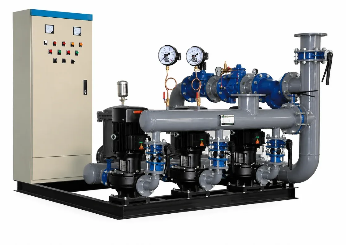
YONGFAN direct-mixing heating skids connect high- and low-zone water circuits directly without intermediate plate heat exchangers across 0.14–4.2 MW loads, 0.5–1.0 MPa working pressures, and 4.8–360 m³/h circulation rates.
Failure of the high-zone return pressure-reducing system transmits 20–60 m hydrostatic static head directly to low-zone radiators.
At 4.2 MW, radiator duty (25 K ΔT) moves 144 m³/h (45 kW pump), whereas floor heating (10 K ΔT) requires 360 m³/h (110 kW pump).
Sudden pump shutdown creates negative pressure at the building top and water hammer at the base without fast-acting solenoid isolation.
Fine welding slag or magnetite blocks precision pilot valves. An integrated dirt separator is essential for reliable pressure control.
Standard radiator duty basis; area based on 70 W/m² building load.
| Capacity (MW) | Heating Area Basis | Water Flow (m³/h) | Pump Motor Power (kW) |
|---|---|---|---|
| 0.14 MW | 2,000 m² | 4.8 | 1.5 |
| 0.21 MW | 3,000 m² | 7.2 | 2.2 |
| 0.35 MW | 5,000 m² | 12.0 | 3.0 |
| 0.56 MW | 8,000 m² | 19.3 | 4.0 |
| 0.70 MW | 10,000 m² | 24.1 | 5.5 |
| 1.05 MW | 15,000 m² | 36.1 | 7.5 |
| 1.40 MW | 20,000 m² | 48.2 | 11.0 |
| 1.75 MW | 25,000 m² | 60.2 | 15.0 |
| 2.10 MW | 30,000 m² | 72.2 | 18.5 |
| 2.80 MW | 40,000 m² | 96.3 | 22.0 |
| 3.15 MW | 45,000 m² | 108.4 | 30.0 |
| 3.50 MW | 50,000 m² | 120.4 | 37.0 |
| 4.20 MW | 60,000 m² | 144.5 | 45.0 |
10 K temperature rise requires 2.5× higher circulation flow and larger pump motors.
| Capacity (MW) | Heating Area Basis | Water Flow (m³/h) | Pump Motor Power (kW) |
|---|---|---|---|
| 0.14 MW | 2,000 m² | 12.0 | 3.0 |
| 0.21 MW | 3,000 m² | 18.1 | 4.0 |
| 0.35 MW | 5,000 m² | 30.1 | 5.5 |
| 0.56 MW | 8,000 m² | 48.2 | 7.5 |
| 0.70 MW | 10,000 m² | 60.2 | 11.0 |
| 1.05 MW | 15,000 m² | 90.3 | 18.5 |
| 1.40 MW | 20,000 m² | 120.4 | 22.0 |
| 1.75 MW | 25,000 m² | 150.5 | 30.0 |
| 2.10 MW | 30,000 m² | 180.6 | 37.0 |
| 2.80 MW | 40,000 m² | 240.8 | 45.0 |
| 3.15 MW | 45,000 m² | 270.9 | 55.0 |
| 3.50 MW | 50,000 m² | 301.0 | 75.0 |
| 4.20 MW | 60,000 m² | 360.0 | 110.0 |
High-efficiency vertical inline pumps sized specifically to boost water across the 20–60 m high-rise elevation head.
High-precision pilot-operated pressure-reducing valves step down high-zone return pressure to match low-zone return limits.
Fast-acting shutoff solenoid valves isolate high- and low-zones in milliseconds upon power failure or pump trip.
Integrated fine mesh strainer and dirt separator removes welding slag and magnetite to protect sensitive pilot valves.
Electric contact pressure gauges monitor high- and low-zone pressure thresholds with automated alarm and pump cutouts.
Supports manual override, local automatic pressure balancing, and remote building management system (BMS) integration.
Height difference between low-zone plant room and high-zone top radiator (20–60 m).
Specify Radiator (25 K ΔT) or Floor Heating (10 K ΔT) loop parameters.
High-zone building envelope heat loss in kW or MW (from 0.14 to 4.2 MW).
System design pressure (0.5–1.0 MPa) and preferred control protocol (BMS/PLC).
YONGFAN engineers will calculate circulation pump head, size pressure-reducing valves, and provide dimensioned 3D CAD skid layouts.
Pressure-reducing pilot valves are calibrated on test rigs across variable flow and pressure ratios to prevent hunting.
All skid pipework, headers, and valve manifolds undergo 1.25× design pressure hydrostatic verification.
Fast-acting power-failure trip solenoids are tested for millisecond closing response under simulated electrical cutoff.
Contact pressure gauge signals, pump sequencing, and BMS communications are 100% loop-tested before dispatch.
Direct-mixing units are engineered for 20 to 60 meters elevation difference (approximately 6 to 20 stories) at 0.5–1.0 MPa working pressure.
Fast-acting automatic shutoff solenoid valves isolate the high-zone return line in milliseconds upon loss of power or pump trip.
Floor heating uses a 10 K ΔT (vs 25 K for radiators), requiring 2.5× higher circulation water flow for the same MW thermal capacity.
No. The unified low-zone make-up system maintains water volume for the entire building through the direct-mixing connection.
Documented standard models cover 0.14 to 4.2 MW per unit across 13 capacity steps.
No. Because high and low zones share the same circulating water, both zones must use compatible water treatment chemistry.
Direct mixing connects fluid circuits directly. If high and low loops require chemical isolation, select Packaged Units (ZS/ZW).
For buildings taller than 60 m, multi-tier staging or isolated plate heat exchange substations must be engineered.
Direct mixing connects water-to-water circuits. For primary steam sources, select Tube or Packaged PHE units.
Direct-mixing units are for closed-loop space heating. For domestic hot water, select Storage Heat Exchangers.
Send your building elevation difference, terminal duty (radiator vs floor heating), calculated heating load, and system pressure. YONGFAN application engineers will size mixing pumps, pressure-reducing valves, and provide complete CAD skid drawings.


