
YONGFAN HVAC - Premium Header
Engineered HVAC & Industrial Air Systems
YONGFAN HVACYOFAN HVAC Home
Plant Room & Hydronic Equipment | YONGFAN
Plant Room Engineering · 6 Equipment Families · 0.6–2.0 MPa

Plant Room & Hydronic Equipment: Matched to Hydraulic Duty & Pressure Regimes

Plant-room equipment must control pressure, water supply, distribution and condensate return as separate duties; combining the wrong functions can destabilize loops or waste available system pressure.

Compare YONGFAN make-up vessels, packaged expansion skids, variable-frequency booster systems, direct non-negative pressure equipment, custom hydronic manifolds, and steam condensate recovery units.

6 Families Make-Up · Skid · Booster · NNP · Manifold · Condensate
Flow Span 1 – 5,500 m³/h
Regulation ≤0.01 MPa Accuracy
Pressure Classes 0.6 / 1.0 / 1.6 / 2.0 MPa
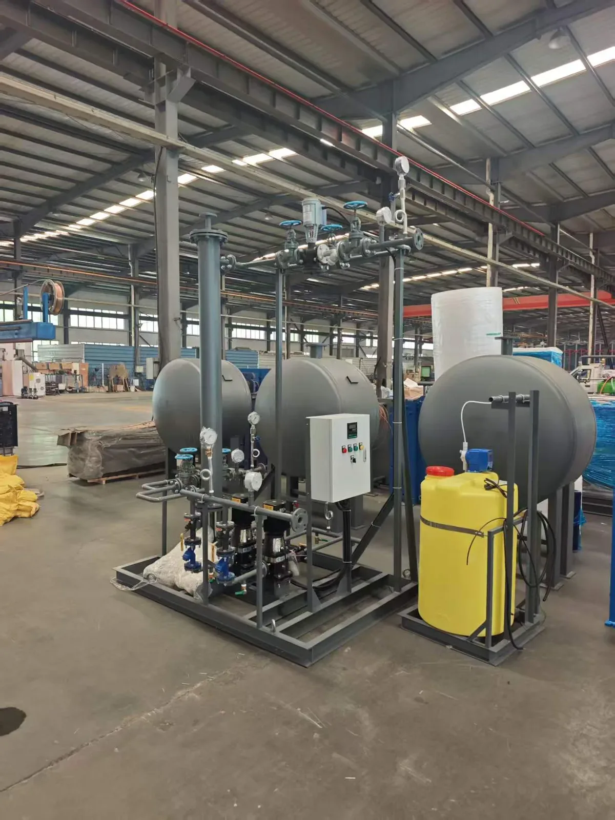
YONGFAN automatic chemical dosing unit
Plant Room Hydronic Engineering Closed-Loop Expansion · Constant-Pressure Boosting · Multi-Branch Headers
01 / System Selection

Plant-Room Failures Start When Equipment Solves the Wrong Pressure Problem

A mechanical room can look complete and still operate poorly because every skid was selected around “pressure” without defining which hydraulic problem each was meant to solve.
YONGFAN multi-media water filter
Hydraulic Reference Point

Why Hydronic Duties Cannot Be Interchanged

Per ASHRAE Hydronic Heating and Cooling, expansion chambers provide thermal expansion volume and system reference pressure, completely distinct from domestic boosters.

Make-Up vs. Thermal Expansion

Make-up pumps replace leakage, while bladder vessels accommodate thermal expansion. An oversized pump cannot replace a properly sized expansion tank.

Impact: Frequent pump cycling & relief valve discharge

Booster Sizing on Static Height Alone

Booster head must account for inlet pressure, friction losses, and fixture residual pressure—not just building floor counts or static height.

Impact: Excessive fixture pressure or top-floor starvation

Direct-Mains Negative Pressure

Connecting a booster directly to municipal mains without suction-side pressure monitoring risks collapsing public supply pressure.

Impact: Backsiphonage hazard & utility violation

Average vs. Peak Condensate Flow

Sizing steam condensate receivers from daily averages causes overflow when multiple batch traps discharge simultaneously.

Impact: Receiver overflow, cavitation & wasted thermal energy

Define the Hydraulic Duty Before Selecting Equipment

Six specialized families engineered to match specific pressure, flow, and temperature boundaries.

01 Closed-Loop Volume & Pressure Band
02 Peak Demand & Municipal Inlet Head
03 Multi-Branch Flow & Header Velocity
04 Condensate Temperature & Peak Return
02 / Portfolio Showcase

Hydronic Plant-Room Portfolio: 6 Equipment Families

From closed-loop bladder expansion and packaged stabilization skids to municipal boosters, manifolds, and steam condensate return systems.
01 · Water Make-Up Units 0.20 to 8.53 m³ · Regulating Vt 0.06–3.10 m³

JFDY Constant-Pressure Water Make-Up Units

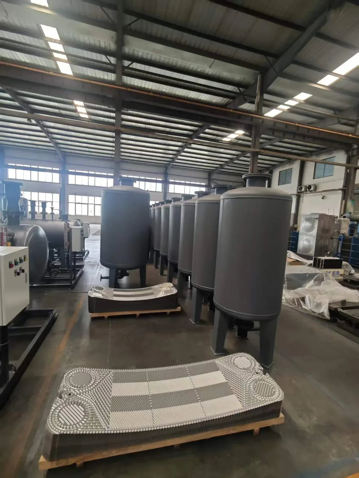
Pre-charged bladder pressure vessels for closed HVAC loops. Replaceable food-grade butyl rubber bladder contains water while a dry nitrogen/air cushion absorbs volume changes. Prevents pump cycling by providing usable regulating volume (Vt) across 0.6, 1.0, and 1.6 MPa classes.

Vessel Total Volume (V)
0.20 – 8.53 m³ (8 sizes)
Regulating Volume (Vt)
0.06 – 3.10 m³
Working Pressure
0.6 / 1.0 / 1.6 MPa
Water Temperature
≤80 °C standard
Primary Applications

Central chilled-water loops, district heating substations, and closed hydronic circuits requiring standalone pressure vessel buffering.

02 · Pressure Stabilizing & Expansion 48 to 480 m³ Loop Water · 2.4–24 m³/h Make-Up

JFWP Packaged Pressure Stabilizing & Expansion Units

Integrated plant-room skid combining automated make-up, dual stainless multistage pumps, pressure stabilization, thermal expansion handling, overpressure relief, auto air venting, and low-water alarms. JFWP-A for compact footprints; JFWP-B with atmospheric expansion tank for bulk expansion retention.

System Water Capacity
48 – 480 m³ (8 sizes)
Rated Make-Up Flow
2.4 – 24 m³/h
Make-Up Pump Head
24 – 112 m (11 steps)
Configurations
JFWP-A (Compact) / JFWP-B (Tank)
Primary Applications

Commercial HVAC mechanical rooms, district heating substations, hospital heating/cooling plants needing fully automated skids.

03 · VFD Water Supply 8 to 5,500 m³/h · 20–250 m Head

JFHB Fully Automatic Constant-Pressure VFD Water Supply Equipment

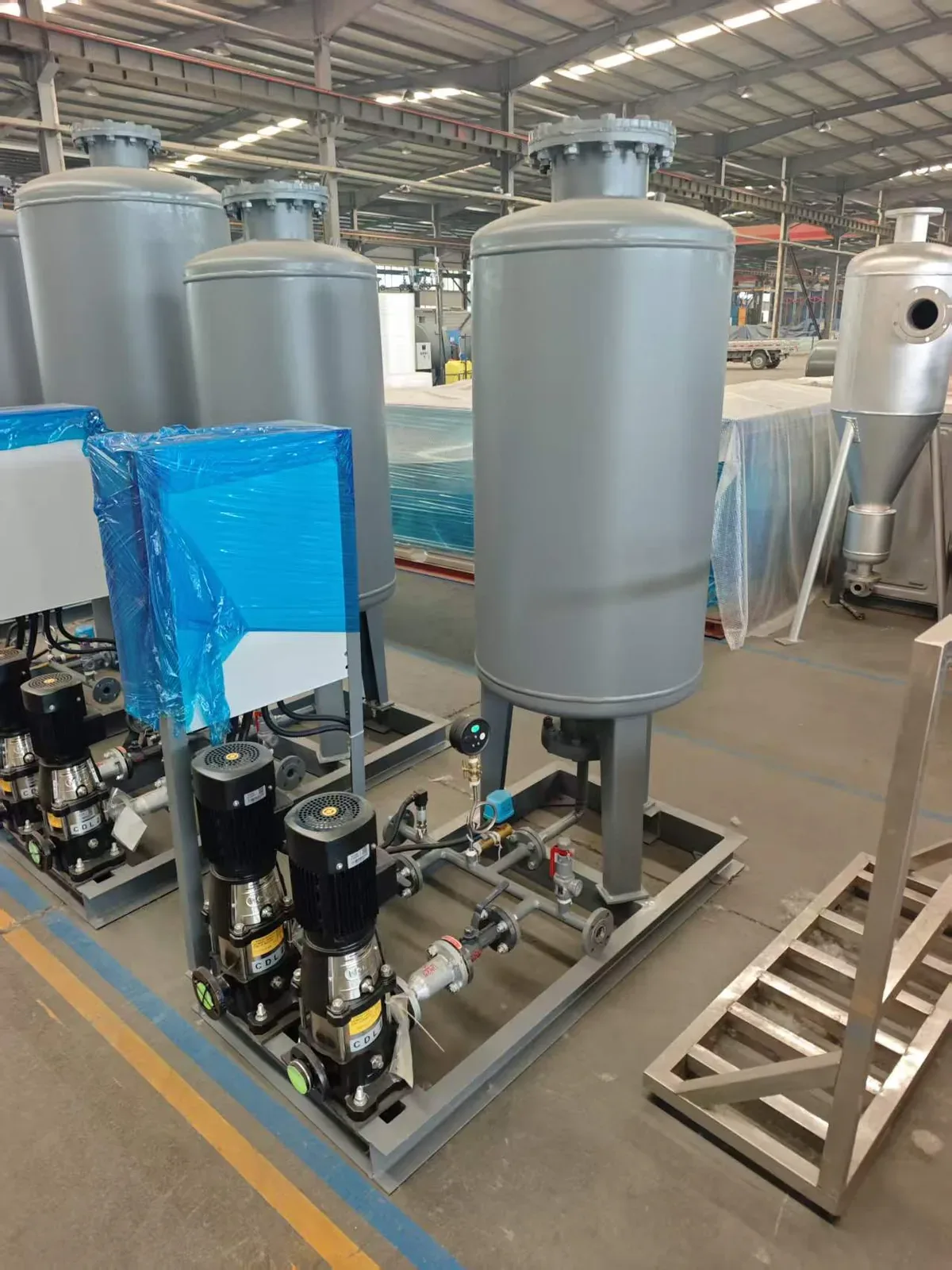
Constant-pressure variable-frequency booster skids with integrated buffer tanks (Φ600–Φ800 mm). Buffer tank holds pressure during low/zero demand so main pumps can sleep. Staging up to 8 pumps in parallel with ≤0.01 MPa pressure regulation accuracy.

Flow Range
8 – 5,500 m³/h
Head Span
20 – 250 m
Motor Power
0.55 – 315 kW
Control Accuracy
≤0.01 MPa · Modbus/BACnet
Primary Applications

Residential communities, high-rise offices, hotels, hospitals, and industrial water systems fed via break tanks or atmospheric storage.

04 · Direct-Mains Boosting 8 to 280 m³/h · Direct Municipal Connection

JFWZ Non-Negative-Pressure Water Supply Equipment

Boosts directly from pressurized municipal mains without an atmospheric break tank. Features an inlet non-negative-pressure vessel (600×1200 to 1800×3000 mm), full-flow bypass when municipal head is sufficient, and automated pump slowdown/cut-off to protect public mains.

Rated Flow
8 – 280 m³/h (Single skid)
Rated Head
20 – 250 m
Inlet Protection
Vacuum suppression sensor
Bypass Feature
100% full-flow direct bypass
Primary Applications

Municipal-approved direct booster connections for commercial towers, hotels, and residential estates seeking energy savings.

05 · Hydronic Headers DN50 to DN500 Main · 2 to 12+ Branches

Water Distributors & Collectors (Custom Manifolds)

Custom-engineered supply distributors and return collectors designed to maintain low header velocity (0.5–1.0 m/s) and eliminate circuit interaction. Available as individual headers or matched mirrored pairs in Q235-B, Q345R, SS304, or SS316L.

Main Header DN
DN50 – DN500 (500–6,000 mm L)
Branch Outlets
DN15 – DN300 (2 to 12+ ports)
Working Pressure
0.6 / 1.0 / 1.6 / 2.0 MPa
Metallurgy
Q235-B / Q345R / SS304 / SS316L
Primary Applications

Central chilled-water plants, multi-boiler loops, district heating zones, and industrial cooling manifolds.

06 · Steam Return 1 to 100 t/h · Up to 150–180 °C

JFLN Condensate Recovery Units

Packaged steam condensate collection and return skids. Incorporates pressure-regulating vessel, anti-cavitation inlet geometry, high-temperature condensate pump (80–180 °C), and automated level switching to return valuable boiler feedwater without flashing.

Recovery Capacity
1 – 100 t/h (JFLN-1 to 100)
Max Condensate Temp
150 °C std (180 °C upgraded)
Connections
DN50/40 up to DN225/175
Cavitation Protection
Internal suction pressure control
Primary Applications

Industrial steam plants, chemical process heating, food & pharma plants, hospital autoclaves, and district steam return networks.

03 / Selection Routing

Hydronic Equipment Family Comparison Matrix

Cross-reference all six YONGFAN hydronic product families by primary engineering role, published capacity boundary, and first selection input.
Product Family What It Solves Published Range Boundary First Input to Confirm Action
Water Make-Up Units Bladder-vessel pressure buffering and regulating volume 0.20–8.53 m³ vessel · 0.6/1.0/1.6 MPa Closed-loop water volume & pressure band Configure JFDY
Pressure Stabilizing & Expansion Integrated make-up, pressure stabilization & thermal expansion 48–480 m³ loop capacity · 2.4–24 m³/h make-up Total closed-loop water volume & A/B style Configure JFWP
VFD Water Supply Equipment Constant-pressure boosted supply from break tanks 8–5,500 m³/h · 20–250 m head Peak demand flow & target pressure Configure JFHB
Non-Negative-Pressure Supply Direct municipal boosting while protecting inlet mains 8–280 m³/h · 20–250 m head Municipal inlet-pressure profile & approval Configure JFWZ
Water Distributors & Collectors Splits and combines multiple hydronic branches DN50–DN500 main · 2–12+ branches · ≤2.0 MPa Total flow & branch flow schedule Configure Manifold
Condensate Recovery Units Returns hot steam condensate without pump cavitation 1–100 t/h nominal · Up to 150–180 °C Peak condensate flow & return temperature Configure JFLN
04 / Procurement Protocol

Information Required for Hydronic Equipment Sizing

A single-line hydraulic schematic with pressure, flow, and temperature values is the most effective starting document.
STEP 01

System Hydraulic Type

Closed HVAC loop, open potable booster, direct-mains connection, or steam condensate.

STEP 02

Flow & Water Volume

Peak flow rate (m³/h), total closed-loop water volume (m³), or peak condensate (t/h).

STEP 03

Pressure & Head Regimes

Inlet pressure (MPa), discharge setpoint, static elevation, and allowable pressure class.

STEP 04

Temperature & Control

Operating temperature range, Modbus/BACnet BMS requirements, and standby redundancy.

Engineering Handoff

Submit Hydronic Parameters for Skid Sizing

YONGFAN application engineers will calculate required vessel volume, pump head, velocity profiles, and provide GA layout drawings.

Total Closed-Loop Volume (m³)
Design Pressure Class (0.6–2.0 MPa)
Peak Demand Flow (m³/h) & Head (m)
Municipal Inlet Pressure Profile
Branch Flow Schedule (Manifolds)
Condensate Temp & Peak Rate (t/h)
05 / Manufacturing Verification

Workshop Fabrication & Calibrated Loop Testing

Manufactured in dedicated workshop facilities with full hydrostatic pressure testing and integrated skid operational sign-off.
Pressure QA

1.5× Hydrostatic Testing

Every JFDY vessel, JFWP circuit, manifold, and JFLN receiver receives 1.5× design pressure testing held for 30 minutes.

Functional QA

Calibrated Loop Run

Booster and expansion skids undergo full operational testing verifying VFD modulation, pump staging, and ±0.01 MPa regulation.

Welding QA

Submerged-Arc Seams

Automated submerged-arc welding on pressure vessels and manifolds with visual and NDT inspection on critical welds.

Electrical QA

IP54/IP65 Cabinets

Control panels undergo hi-pot insulation checks, ground continuity tests, and PLC sequence verification before dispatch.

Bespoke Engineering: Hydraulic calculations, 3D CAD models, and electrical schematics provided with submittals. Trade Terms: EXW, FOB, CIF, CFR, and DDP export logistics supported globally.
06 / Engineering Knowledge

Plant Room & Hydronic Equipment FAQ

Direct engineering answers regarding closed-loop selection, direct boosting, manifolds, and steam condensate return.

Which family should I use for a closed chilled-water loop?

Start with Pressure Stabilizing & Expansion Units (JFWP) when you need integrated make-up and expansion control. Use Water Make-Up Units (JFDY) when the bladder pressure vessel is the primary component being specified.

Is JFHB an HVAC expansion unit?

No. VFD Water Supply Equipment (JFHB) is a variable-demand booster system for domestic/process water. Closed-loop expansion and pressure stabilization belong to JFDY or JFWP.

What is the main difference between JFHB and JFWZ?

Non-Negative-Pressure Water Supply (JFWZ) connects directly to an approved municipal main and uses available inlet head. JFHB is designed for systems fed from atmospheric break tanks.

Which product divides one plant loop into several zones?

Use Water Distributors & Collectors. The manifold is customized from total flow, branch count, branch sizes, and system pressure.

Can a distributor/collector replace a pump?

No. Distributors and collectors balance and combine fluid streams; they do not generate pump differential pressure.

Which product handles steam condensate?

Use Condensate Recovery Units (JFLN). JFLN is selected from peak condensate flow and temperature and sits downstream of steam traps.

07 / Application Boundaries

Plant Room Engineering Boundaries

Understanding hydraulic limits before confirming final plant equipment schedules.
Boundary 01 / Make-Up Duty

No Booster for Loops

Do not use a domestic-water booster to stabilize a closed hydronic heating or cooling loop.

Boundary 02 / Direct Boosting

Authority Approval

Do not connect JFWZ directly to municipal mains without confirming local water authority approval.

Boundary 03 / JFDY Scope

Vessel vs. Skid

JFDY is the bare pressure vessel; pumps, valves, and controls must be specifically ordered if a skid is needed.

Boundary 04 / Steam Condensate

Peak vs. Average

Do not size JFLN condensate units from average hourly return when batch processes create high short-term surges.

08 / Engineering Handoff

Select the Right Hydronic Equipment for Your Plant Room

Send your hydraulic schematic, design flow, pressure regimes, and operating temperatures. YONGFAN application engineers will verify vessel volumes, pump heads, and provide complete submittal drawings.

Flow: 1–5,500 m³/h Vessel Volumes: 0.20–8.53 m³ 0.6 / 1.0 / 1.6 / 2.0 MPa Classes Regulation: ≤0.01 MPa Modbus RTU / BACnet IP 1.5× Hydrostatic Tested
YONGFAN ambient-temperature filtration deaerator
Direct Application Engineering Support
Hydraulic volume calculations, pump head sizing & submittal drawings.