VFD water supply equipment must match peak demand, required pressure, pump staging and inlet conditions; a poorly selected booster can waste energy or cycle excessively at low flow.
YONGFAN JFHB Fully Automatic Constant-Pressure VFD Water Supply Equipment combines pressure feedback, variable-speed pump staging (up to 8 pumps), ≤0.01 MPa accuracy, and an integrated buffer tank (Φ600–Φ800 mm) for zero-demand pump sleep.
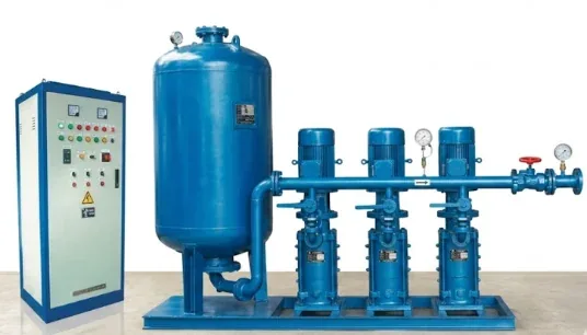
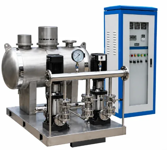
Selecting one large pump for peak morning draw forces it to run at deep low-frequency turndown overnight, wasting energy and overheating pump casing.
VFDs slow pumps down, but without an integrated buffer tank to hold pressure, pumps cannot sleep during zero demand without pressure dropping.
JFHB is engineered for break-tank or atmospheric storage suction. For direct municipal boosting without break tanks, select JFWZ Non-Negative-Pressure equipment.
Booster head must include suction water level, pipe/valve friction losses, and required fixture residual pressure (e.g. 0.1–0.2 MPa), not just elevation.
| Model | Rated Flow (m³/h) | Rated Head (m) | Outlet DN | Pump Family | Motor Power | Buffer Tank |
|---|---|---|---|---|---|---|
| JFHB8-20-2-600L | 8 | 20 | DN32 | ISG Inline | 0.75 kW | Φ600 mm |
| JFHB12-30-2-600L | 12 | 30 | DN50 | LG Vertical Multistage | 1.5 kW | Φ600 mm |
| JFHB12-120-2-600L | 12 | 120 | DN50 | LG Vertical Multistage | 5.5 kW | Φ600 mm |
| JFHB22-30-2-600L | 22 | 30 | DN80 | LG Vertical Multistage | 2.2 kW | Φ600 mm |
| JFHB22-120-2-600L | 22 | 120 | DN80 | LG Vertical Multistage | 7.5 kW | Φ600 mm |
| JFHB45-40-2-600L | 45 | 40 | DN100 | LG Vertical Multistage | 5.5 kW | Φ600 mm |
| JFHB65-100-2-600L | 65 | 100 | DN125 | LG Vertical Multistage | 18.5 kW | Φ600 mm |
| JFHB90-120-2-600L | 90 | 120 | DN150 | LG Vertical Multistage | 30.0 kW | Φ600 mm |
*Wider custom skids cover up to 5,500 m³/h, 250 m head, and 315 kW with up to 8 pumps in parallel cascaded control.
The discharge pressure transmitter feeds measured pressure to the PLC. A PID loop modulates VFD frequency to maintain setpoint accuracy within ≤0.01 MPa across shifting fixture draw.
As demand exceeds single-pump capacity, auxiliary pumps start in stages. Lead pump continues VFD modulation to trim flow. Programmable rotation balances running hours across all pumps.
During zero consumption, the pre-pressurized buffer tank absorbs small leakage and holds line pressure. When pressure stays within band, all pumps shut down until pressure falls below cut-in threshold.
Probabilistic peak flow (m³/h) from plumbing fixtures or process equipment.
Suction tank water level and required pressure at the highest/remotest fixture.
Number of working pumps and standby philosophy (e.g. 2W+1S or 3W+1S).
Modbus RTU standard, BACnet IP gateway, cabinet IP rating, and alarm contacts.
YONGFAN application engineers will calculate pump staging curves, select buffer tank volume, and provide complete GA drawings.
LG vertical multistage and ISG pumps verified with factory hydrostatic certificates and performance curves.
Pressure regulation accuracy verified at ±0.01 MPa with calibrated reference transmitters and soft-start ramps.
Factory sequence tests verify cascaded pump staging, pump rotation, dry-run cut-off, and low-flow buffer sleep.
Control panels undergo hi-pot insulation checks, ground continuity tests, and manual bypass mode checks.
YONGFAN states an overall range of 8–5,500 m³/h, 20–250 m head, and 0.55–315 kW motor power across standard and custom skids.
The JFHB buffer tank holds pressurized water during low or zero demand so the main pumps can stop until network pressure falls below the restart setpoint.
The control architecture supports cascaded sequencing of up to 8 pumps in parallel with programmable lead-pump rotation.
YONGFAN achieves ≤0.01 MPa pressure-regulation accuracy and verifies the control loop on a calibrated factory test rig.
Yes. RS-485 / Modbus RTU is standard. BACnet MS/TP and BACnet/IP gateways are available on request.
Not when direct connection to public mains is required. Use Non-Negative-Pressure Water Supply (JFWZ) when local regulations permit direct boosting.
Do not use a single booster for tall buildings without dividing lower zones with pressure-reducing valves or separate sets.
Do not select one large pump for peak demand without verifying the normal overnight low-demand operating point.
JFHB requires an acceptable positive suction source (such as a break tank) and does not include municipal inlet protection.
The buffer tank provides local pressure-hold and damping, not complete water-hammer protection for long cross-country mains.
Send your peak demand flow, required discharge pressure, and suction water conditions. YONGFAN application engineers will verify pump staging curves, select buffer tank volume, and provide complete submittal drawings.


