Non-negative-pressure water supply must match peak demand, municipal inlet pressure and local approval; the wrong booster can depress the public main or waste available supply pressure.
YONGFAN JFWZ Non-Negative-Pressure Water Supply Equipment preserves available municipal inlet head, adds only the required pressure deficit, and includes automated vacuum suppression to protect public water mains.
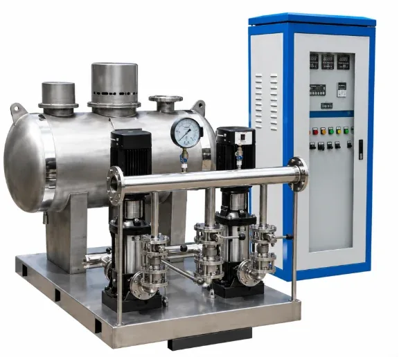
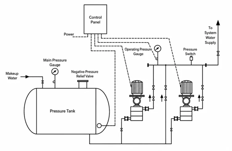
Sizing the pump for 100% outlet pressure from zero wastes energy. JFWZ utilizes existing 20–30 m municipal pressure and only adds the pressure deficit.
An afternoon static pressure reading is useless; inlet head must be measured during peak municipal demand hours to ensure adequate suction head.
Non-negative-pressure control does not grant permission by itself. Local water authority approval and backflow regulations always govern installation.
The non-negative-pressure vessel manages inlet pressure transients; it is not an atmospheric reserve tank for hours of emergency building water supply.
| Model | Rated Flow (m³/h) | Rated Head (m) | Pump Family | Motor Power | NNP Tank Dimensions |
|---|---|---|---|---|---|
| JFWZ8-20-2-600L | 8 | 20 | ISG32-125 | 0.75 kW | 600 × 1200 mm |
| JFWZ12-45-2-800L | 12 | 45 | LG Vertical Multistage | 2.2 kW | 800 × 1400 mm |
| JFWZ22-80-2-1000L | 22 | 80 | ISG50-250 | 11.0 kW | 1000 × 1500 mm |
| JFWZ45-80-2-1200L | 45 | 80 | ISG65-250 | 15.0 kW | 1200 × 1500 mm |
| JFWZ90-80-2-1400L | 90 | 80 | ISG80-250 | 22.0 kW | 1400 × 2000 mm |
| JFWZ180-80-2-1600L | 180 | 80 | ISG100-250 | 37.0 kW | 1600 × 2500 mm |
| JFWZ280-80-2-1800L | 280 | 80 | ISG125-250 | 55.0 kW | 1800 × 3000 mm |
*Standard skids feature 2 working pumps + 1 standby. Overall JFWZ platform supports custom engineered booster sets up to 250 m head.
When municipal pressure is high enough to meet downstream demand, pumps sleep and water flows 100% through the parallel bypass without consuming pump electrical power.
When inlet pressure drops below target outlet setpoint, VFD pumps modulate to add only the exact missing pressure head, preserving the energy already in the incoming main.
The suction pressure transmitter continuously monitors the NNP tank. If municipal pressure nears the low-pressure safety threshold, the PLC reduces pump speed or shuts down to protect public mains.
Design peak flow rate (m³/h) from building fixture count or process load.
Minimum, average, and peak-hour municipal main pressure (MPa).
Building elevation height, pipe losses, and fixture residual head requirements.
Local water utility direct-connection permission and backflow regulations.
YONGFAN application engineers will calculate differential head, select NNP tank dimensions, and provide certified GA submittal drawings.
Verified response when inlet pressure drops to threshold: smooth pump deceleration and complete dry-run shutdown.
Direct bypass flow path tested under full rated flow with pumps de-energized to ensure zero excessive pressure loss.
Tank rolled and longitudinally welded with submerged-arc process, internal anti-corrosion lining, and 1.5× hydrostatic test.
VFD soft-start ramps, pump alternation, auto-restart upon pressure recovery, and Modbus/BACnet data points tested.
The standard single-skid selection range is 8–280 m³/h with head coverage from 20 to 250 m.
The JFWZ full-flow bypass passes water directly to the building with the booster pumps completely powered down.
The non-negative-pressure controller reduces pump speed or shuts down the skid to prevent pulling the public main into negative pressure.
No. JFWZ connects directly to municipal mains. That is the main physical difference from break-tank booster sets.
JFWZ connects directly to pressurized municipal mains with suction protection. JFHB is for systems fed from atmospheric break tanks.
Yes. RS-485 / Modbus RTU is standard. BACnet gateways are available for building automation systems.
Do not specify JFWZ where local water utilities prohibit direct booster connection to the public main.
Do not size pump head from outlet pressure alone; calculate the actual differential head needed above minimum inlet pressure.
Do not interpret the NNP vessel as emergency storage; if fire/process storage is required, provide dedicated break tanks.
Do not use a single high-head booster for an entire tower without dividing lower levels into pressure-controlled zones.
Send your peak demand flow, municipal inlet pressure profile, and target discharge head. YONGFAN application engineers will verify differential pump sizing, NNP tank volume, and provide certified submittal drawings.


