YONGFAN HVAC - Premium Header
Engineered HVAC & Industrial Air Systems
YONGFAN HVACYOFAN HVAC Home
Condensate Recovery Units | JFLN Series | YONGFAN
Steam Condensate Return · JFLN Series · 1–100 t/h

Condensate Recovery Units: High-Temperature Return Without Pump Cavitation

Condensate recovery units must match peak return flow, condensate temperature and discharge pressure; the wrong receiver or pump can overflow, cavitate or waste recoverable heat.

YONGFAN JFLN Condensate Recovery Units combine pressurized collection vessels, anti-cavitation suction geometry, specialized high-temperature pumps (up to 150–180 °C), and automatic level control across 10 standard sizes.
10 Sizes (JFLN) 1 – 100 t/h Nominal
Max Temp 150 °C std / 180 °C upg
Anti-Cavitation Suction Pressure Control
Level Control Automated Cut-In/Cut-Out
Industrial steam condensate recovery unit with high-temperature pumps and receiver vessel
High-Temperature Condensate Recovery Anti-Cavitation Suction · Automated Level Cycling · GB150 Tested
01 / Thermal Hydraulics

Hot Condensate Becomes a Problem When Suction Pressure Falls Too Far

Condensate leaving steam equipment is near saturation temperature. When pressure falls at the pump impeller eye, vapor bubbles form and collapse violently—destroying impellers and causing recovery failure.
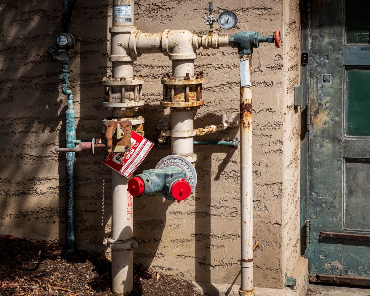
Steam plant condensate pipework and boiler feed tank
Boiler Energy Recovery

Why Returning Hot Condensate Maximizes Boiler Efficiency

Per U.S. DOE Steam Tip Sheet 8, returning hot condensate directly saves boiler fuel, treatment chemicals, and raw makeup water.

Sizing on Daily Average Flow

Batch processes and simultaneous trap discharges create sharp short-term peak return surges. Sizing on daily average flow causes receiver overflow.

Impact: Receiver vessel overflow & water loss

Ignoring Water Temperature

Pumps handling 40 °C water cavitate destructively on 120–150 °C condensate without specialized mechanical seals and suction pressure boosting.

Impact: Severe pump cavitation & impeller erosion

Replacing Steam Traps

JFLN does not replace upstream steam traps. Steam traps remain at each individual process heat exchanger to discharge condensate into the return header.

Impact: Steam blow-through into return header

Contamination Ingress

Process leaks can contaminate returned condensate. Critical duties require conductivity monitoring and automated dump valves upstream of JFLN.

Impact: Boiler tube fouling & carryover

Four Parameters Required for JFLN Sizing

Verified against GB 150 & TSG 21 pressure vessel standards.

01 Peak Condensate Return (t/h)
02 Condensate Temperature (°C)
03 Delivery Destination & Backpressure
04 Contamination Monitoring Plan
02 / Model Portfolio

JFLN Series Model Table: 10 Recovery Capacity Steps

Model suffixes correspond approximately to rated condensate recovery capacity in tonnes per hour under typical steam plant conditions.
Model Approx. Nominal Capacity Condensate Inlet D₁ Discharge Outlet D₂
JFLN-1 1 t/h DN50 DN40
JFLN-2 2 t/h DN65 DN50
JFLN-4 4 t/h DN80 DN65
JFLN-6 6 t/h DN80 DN80
JFLN-10 10 t/h DN100 DN80
JFLN-20 20 t/h DN125 DN100
JFLN-35 35 t/h DN150 DN125
JFLN-50 50 t/h DN200 DN150
JFLN-75 75 t/h DN200 DN150
JFLN-100 100 t/h DN225 DN175

*Inlet D1 is sized larger to accommodate two-phase return flow; outlet D2 is sized for pumped liquid delivery.

03 / Hydraulic Engineering

Cavitation Suppression & High-Temperature Pumping

Three coordinated engineering elements maintain positive NPSH margin and prevent steam flashing inside the recovery pump.

Pressure-Regulated Receiver

Maintains internal receiver pressure relative to condensate saturation temperature, preventing flash steam from venting to atmosphere and preserving thermal energy.

Cavitation Suppression Baffles

Internal vessel baffles and specialized suction geometry minimize local velocity heads and friction drops right before the pump impeller eye.

High-Temperature Pump Trims

Heavy-duty mechanical seals, high-temperature bearings, and specialized impeller metallurgy engineered for continuous 80–180 °C duty.

04 / Procurement Protocol

Information Required for Accurate JFLN Sizing

Do not select JFLN from average daily tonnage. Submit peak condensate return profile, temperature, and delivery destination pressure.
STEP 01

Peak Return Rate

Simultaneous peak condensate mass flow rate (t/h) from all steam users.

STEP 02

Condensate Temperature

Design operating return temperature (up to 150 °C std / 180 °C upgraded).

STEP 03

Discharge Destination

Deaerator or boiler feedwater tank elevation and operating backpressure.

STEP 04

Contamination & Metals

Receiver material (Q235-B / SS304 / SS316L) and conductivity dump logic.

Engineering Handoff

Submit Steam System Parameters for JFLN Sizing

YONGFAN engineers will calculate receiver surge buffering, select high-temp pump head, and provide certified GA submittal drawings.

Peak Condensate Flow (1–100 t/h)
Condensate Temp (up to 180 °C)
Feedwater Tank Backpressure (MPa)
Receiver Metallurgy: Carbon / SS304 / SS316L
Upstream Steam Pressure (MPa)
BMS Protocol: Modbus RTU / SCADA
05 / Manufacturing Quality

Pressure Vessel Rolling & Hot-Water Loop Validation

Fabricated to GB 150 pressure standards with 1.5× hydrostatic testing and calibrated hot-water functional testing.
Vessel QA

GB 150 Vessel Rolling

Longitudinally submerged-arc welded pressure receiver with visual, radiographic NDT, and serial traceability.

Pressure QA

1.5× Hydrostatic Hold

Receiver shell and suction interfaces tested at 1.5× working pressure for 30 minutes with zero leakage.

Hot Loop QA

Thermal Loop Test

Operated on a calibrated hot-water test loop simulating near-saturation conditions to verify cavitation-free pumping.

Controls QA

Level Cycling Check

Automated level cut-in/cut-out, dry-run safety cutoffs, and Modbus RTU data points verified before crating.

Lead Time: 25–35 working days (JFLN-1 to JFLN-20); 35–50 working days (JFLN-35 to JFLN-100). Trade Terms: EXW, FOB, CIF, CFR, and DDP export logistics supported globally.
06 / Engineering Knowledge

Condensate Recovery Units FAQ

Direct engineering answers regarding JFLN capacity ratings, temperature limits, steam trap interaction, and contamination.

What is the JFLN capacity range?

Ten standard models run from JFLN-1 to JFLN-100, corresponding approximately to 1–100 t/h nominal recovery capacity.

What is the standard maximum condensate temperature?

Standard JFLN units handle up to 150 °C. Upgraded configurations handle up to 180 °C with specialized mechanical seals and pump metallurgy.

Does JFLN replace steam traps?

No. Steam traps remain upstream at each process heat exchanger. JFLN collects the discharged liquid and pumps it toward the boiler feed tank.

Should I size JFLN from average or peak flow?

Always size from peak condensate flow. The receiver buffers short surges, but pump-out capacity must prevent tank overflow.

Can several condensate headers feed one JFLN?

Yes. Multiple return lines can connect to one receiver header provided all stream temperatures and peak flows are coordinated.

What if returned condensate may be contaminated?

Specify upstream strainers and conductivity-triggered reject dump valves to divert off-spec condensate before it enters the boiler return line.

07 / Application Boundaries

JFLN Engineering Boundaries

Key engineering rules for steam condensate collection and boiler return.
Boundary 01 / Upstream Traps

Maintain Steam Traps

Do not attempt to replace defective steam traps with a condensate recovery skid; traps must maintain steam seal.

Boundary 02 / Batch Surges

Size for Peak Flow

Do not size from daily average tonnage when batch autoclaves or dryers dump large short-term condensate surges.

Boundary 03 / High Temperature

Check NPSH Margin

Do not assume standard water pumps can handle near-saturation condensate; verify anti-cavitation suction geometry.

Boundary 04 / Quality Verification

Contamination Dump

Do not return suspect industrial process condensate to boilers without automated conductivity monitoring.

08 / Engineering Handoff

Select the Right JFLN Condensate Recovery Unit

Send your peak condensate flow rate, return temperature, and boiler feed tank backpressure. YONGFAN application engineers will verify receiver surge volume, high-temp pump head, and provide certified submittal drawings.


Capacity: 1–100 t/h Temp: Up to 150–180 °C Anti-Cavitation Suction Control Connections: DN50/40 to DN225/175 GB 150 & TSG 21 Compliant Hot-Water Loop Tested
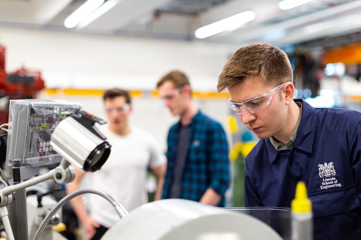
YONGFAN application engineers reviewing condensate recovery skid drawings
Direct Application Engineering Support
Peak flow sizing, anti-cavitation verification & certified GA submittals.
