
YONGFAN HVAC - Premium Header
Engineered HVAC & Industrial Air Systems
YONGFAN HVACYOFAN HVAC Home
HVAC Controls & Valves | YONGFAN
7 Product Families · Thermostats · Actuators · Control · Balancing · Hydraulic

HVAC Controls & Valves: Matched to Control Sequence, ΔP & Interface

Choosing the wrong controller, actuator, balancing device or valve can cause unstable room control, incorrect branch flow, leakage, excessive pump head or failed commissioning.

Explore YONGFAN thermostats (DA / DB / K206), sensors and floating controllers (TC-8000), thermal and motorized linear actuators (VA Series), FCU and AHU control valves (EDV / KYQ), dynamic balancing valves (BYF / KYEJ), 100X–900X pilot hydraulic valves, and general HVAC line valves.

7 Families Thermostats to Hydraulics
Thermostats DA Valve-Only / DB + Fan
Control Valves DN15–DN100 · On/Off & Mod
Hydraulic Range 100X–900X · DN50–DN1200+
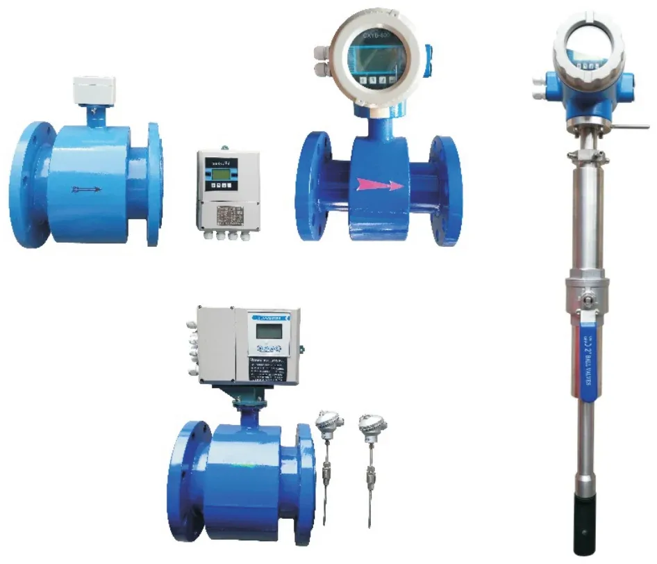
YONGFAN KYLD electromagnetic flowmeter and energy meter
Complete Hydronic Control Loops Terminal Thermostats · Motorized Control · Dynamic Balancing · Pilot Hydraulics
01 / System Integration

Control-Loop Mismatches Appear During Commissioning

An FCU room thermostat calls for cooling but room temperature swings because the fan sequence, actuator stroke, or branch balancing was selected in isolation.
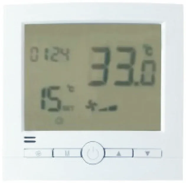
YONGFAN K08 digital fan-coil thermostat
Control Loop Architecture

Why Components Must Be Sized as One Loop

Per ASHRAE Hydronic Valves Guidance, control, balancing, and pressure-regulating devices serve distinct functions and interact dynamically across partial-load operation.

Thermostat Fan Sequence Mismatch

Installing a valve-only thermostat (DA) where the occupant expects 3-speed fan switching (DB) leaves fan speeds unmanaged at setpoint.

Impact: Continuous unwanted fan noise or stagnant room air

Actuator Supply Voltage Conflict

Wiring 230 V line-voltage thermostats directly to 24 V valve actuators destroys actuator coils without interposing transformers.

Impact: Burnt actuator electronics & site rewiring rework

Balancing Valve ΔP Starvation

Operating dynamic balancing valves below 20 kPa leaves internal regulators unengaged, allowing uncontrolled overflow into index branches.

Impact: Unequal hydronic flow distribution & chilled-water deficit

Hydraulic Pilot Dirt Fouling

Omitting upstream strainers before 100X–900X pilot circuits allows pipe scale to plug small orifices, causing main valve hunting or sticking.

Impact: Loss of downstream pressure reduction or tank overflow

The Four Hard Rules of HVAC Control Selection

Architectural function comes before nominal diameter, supply voltage, or pipe connection.

01 / Sequence Define exact valve and fan behavior required at room setpoint
02 / Interface Match actuator stroke, thrust (110 N), thread (M30×1.5), and voltage
03 / Authority Size control valves from design flow and available ΔP, not pipe DN
04 / Balancing Operate within 20–300 kPa ΔP envelope to avoid pump head waste
02 / Portfolio Showcase

HVAC Controls & Valves Product Families

Detailed engineering review of YONGFAN’s seven core controls and hydronic valve families from room-level thermostats to plant-room pilot valves.
01 · Thermostats Room FCU Sequencing

Fan Coil Thermostats (DA / DB / K206)

DA (K-01) controls the motorized valve while the fan runs independently. DB (K Series) controls the valve and 3-speed fan synchronously (AC 180–260 V, <1 W, ±1 °C). K206 provides mechanical dial control with built-in master switch and 220 V to 24 V step-down output.

DA Control Mode
Valve Only (Independent Fan)
DB Control Mode
Valve + 3-Speed Fan Sync
Supply Voltage
AC 180–260 V, 50/60 Hz
Setpoint / Accuracy
5–35 °C · ±1 °C
Primary Use Cases

Hotels, commercial offices, and apartments requiring room-level FCU heating/cooling temperature control.

02 · Sensors & Controllers Measured-Variable Control

HVAC Sensors & Controllers

TC-8000 electronic/LCD floating-point controllers (0–40 °C / 0–99 °C) paired with NTC 10k sensors (0–150 °C, IP54). P74JA3 differential-pressure threshold switches (0.5–4 MPa), HFS paddle flow switches (15 bar, SPDT), and packaged temperature/DP control cabinets.

TC-8000 Range
0–40 °C (Elec) / 0–99 °C (LCD)
Sensor Element
NTC 10k · 0–150 °C · IP54
P74JA3 Setting
0.5–4 MPa DP Threshold
HFS Flow Switch
SPDT · 15 bar · 100,000 Cycles
Primary Use Cases

AHU discharge temperature modulation, chiller proof-of-flow interlocks, and hydronic differential-pressure monitoring.

03 · Actuators Thermal & Motorized Linear

HVAC Valve Actuators (Thermal & VA Series)

Thermal actuators with PTC wax element (M30×1.5, 110 N thrust, 2 VA, 3–5 min stroke, NC/NO, 230/24/110 V). VA motorized linear actuators (VA3100/VA3200/VA7200 on/off 30 mm; VA7400 modulating 30/38 mm with 0–10 V, 4–20 mA, feedback & manual override).

Thermal Actuator
M30×1.5 · 110 N · 2 VA · NC/NO
VA3100 / VA7200
30 mm Linear Stroke · On/Off
VA7400 Modulating
0–10 V / 4–20 mA · Feedback
Enclosure Rating
IP44 (Thermal) / Flame-Retardant
Primary Use Cases

Radiant floor manifolds, FCU terminal valves, AHU heating/cooling coil modulating valves, and plant room control loops.

04 · Motorized Control Valves Terminal to Plant Room · DN15–DN100

Motorized Control Valves (FCU / EDV / KYQ / VG3000)

FCU 2-way replacement valves (DN15–DN25, Johnson/Siemens/Honeywell footprints), 3-wire on/off ball valves, 2-wire fail-in-place ball valves, EDV dynamic balancing 2-way valves (DN20/DN25, 4 bar close-off), KYQ modulating ball valves (DN32–DN100, AC 24 V, spring return), and VG3000 proportional globe valves.

FCU Replacement
DN15, DN20, DN25 · Split & Spring
EDV PICV Terminal
DN20/DN25 · PN16 · 4 bar Close-off
KYQ Modulating
DN32–DN100 · AC 24 V · Spring Return
VG3000 Globe
PN1.6 MPa · Equal-Percentage
Primary Use Cases

FCU zone on/off control, pressure-independent coil balancing, AHU modulating temperature control, and plant loops.

05 · Balancing Valves Hydronic Distribution · DN15–DN800

HVAC Balancing Valves (DRV / KPF / BYF / ZYC / KYEJ)

DRV & KPF static manual balancing valves (DN15–DN600, lockable setting, ±5% accuracy). BYF & B-Type dynamic automatic balancing valves (DN15–DN800, 20–300 kPa ΔP). ZYC self-actuated differential-pressure controllers, and KYEJ electric static balancing valves (0–10 V / 4–20 mA, flow verification).

DRV / KPF Static
DN15–DN600 · Lockable · ±5% Acc
BYF Dynamic Flow
DN15–DN250 · 20–300 kPa ΔP
ZYC DP Controller
Supply/Return Pressure Sensing
KYEJ Electric Static
AC 24 V · 0–10 V / 4–20 mA
Primary Use Cases

Proportional commissioning of constant-flow branches, automatic flow limitation under varying ΔP, and branch DP stabilization.

06 · Hydraulic Control Valves Pilot-Operated · 100X to 900X

Hydraulic Control Valves (100X–900X Series)

Pilot-operated main valve platform (diaphragm ≤DN450 / piston ≥DN500, PN1.0/1.6/2.5 MPa, 0–80 °C). 100X Remote Float, 200X Pressure Reducing, 300X Slow-Closing Check, 400X Flow Control, 500X Relief/Sustaining, 600X Electric Control, 700X Pump Control, 800X DP Bypass, and 900X Emergency Shut-Off.

Construction
Diaphragm ≤DN450 · Piston ≥DN500
Pressure Classes
PN 1.0 / 1.6 / 2.5 MPa
Operating Energy
Pipeline Water Pressure (Pilot)
Functions Covered
Level, PRV, Check, Flow, Relief, DP
Primary Use Cases

High-rise riser pressure reduction, pump station surge/check protection, tank level control, and variable-flow HVAC DP bypass.

07 · General HVAC Valves Manual Isolation · Line Duty

General HVAC Valves (Brass, Stainless, Butterfly & Gate)

Brass threaded valves (ISO 228, PN16, -20–120 °C: ball, gate, stop, check, Y-strainer, air vent, Y13X PRV). 304/316 stainless threaded valves. Butterfly valves (D71X wafer, D371X lug, D341X flanged, SD341X telescopic, D373H metal hard-sealed up to 550 °C, DN50–DN2000). Resilient-seated gate valves (Z45X/Z41X).

Brass Threaded
ISO 228 · PN 1.6 MPa · -20–120 °C
Stainless Threaded
304 / 316 · BSPT / NPT / DIN 2999
Butterfly Valves
DN50–DN2000 · Wafer / Lug / Flange
D373H Hard-Sealed
80–550 °C · Triple-Eccentric
Primary Use Cases

Manual plant room isolation, check backflow prevention, pipeline debris straining, high-point air venting, and distribution headers.

03 / Selection Routing

HVAC Controls & Valves Comparison Matrix

Cross-reference all seven YONGFAN controls and valve product families by problem solved, published boundary, and first selection input.
Product Family What It Solves Published Range Boundary First Input to Confirm Action
Thermostats Room-level FCU temperature and fan/valve sequencing DA valve-only; DB valve + 3-speed fan; AC 180–260 V, 5–35 °C Required sequence at setpoint & fan speed wiring View Thermostats
Sensors & Controllers Measured temperature, pressure status and controller output TC-8000 (0–40/99 °C), NTC 10k (0–150 °C), P74JA3 (0.5–4 MPa), HFS Controlled variable and required output signal View Controllers
Actuators Converts electrical command into valve mechanical stroke Thermal M30×1.5, 110 N, 2 VA, NC/NO; VA 30/38 mm linear Valve stem interface and unpowered fail position View Actuators
Motorized Control Valves On-off or proportional water-flow control across coils FCU 2-way DN15–DN25; EDV PICV DN20/DN25; KYQ DN32–DN100 Flow-control mode (On/off vs Mod), DN & ΔP View Control Valves
Balancing Valves Maintains or adjusts branch/terminal design hydronic flow DRV/KPF static; BYF dynamic DN15–DN250; 20–300 kPa, PN1.6 MPa Design branch flow & available differential pressure View Balancing
Hydraulic Control Valves Pressure, level, pump, flow and DP functions on large mains 100X–900X, diaphragm ≤DN450 / piston ≥DN500, PN1.0/1.6/2.5 MPa Hydraulic function, pipe DN & pressure grade View Hydraulics
General HVAC Valves Isolation, check, straining, venting and manual pressure reduction Brass ISO 228, PN16; Stainless 304/316; Butterfly DN50–DN2000 Pipe function, body material & connection type View General Valves
04 / Procurement Protocol

Information Required for Complete Control Loop Sizing

Submit complete control sequences, hydronic schematics, fan wiring, valve close-off ΔP, and available power voltages.
STEP 01

Control Narrative

FCU fan sequence at setpoint (independent vs stop), modulating vs on/off loop action.

STEP 02

Hydronic Flow & ΔP

Design flow rate (m³/h, L/s), fluid temperature, and available branch differential pressure.

STEP 03

Electrical Signals

Supply voltage (230 V / 24 V), control signal (3-wire, 0–10 V, 4–20 mA, floating).

STEP 04

Fail-Safe Position

Specify unpowered fail state: Normally Closed (NC), Normally Open (NO), or Fail-in-Place.

Engineering Handoff

Submit System Data for HVAC Controls & Valves Sizing

YONGFAN application engineers will verify valve authority, match actuator torque and stroke, check thermostat wiring, and provide unified control submittals.

Control Narrative & Fan Sequence
Supply Voltage: 230 V vs 24 V
Actuator Signal (0–10 V / 4–20 mA)
Close-Off Differential Pressure ΔP
Branch Design Flow & Pipe DN
Hydraulic Function (100X to 900X)
05 / Manufacturing QA

Line-Specific Production & Loop QA Testing

YONGFAN applies automated SMT optical inspection, 100% powered burn-in aging, and hydrostatic valve loop testing across every control product family.
Electronics QA

AOI & 100% Powered Burn-in

DA/DB thermostat and TC-8000 controller PCBs undergo automated optical inspection and powered heat-chamber aging.

Valve Hydro QA

1.5× Pressure Shell Testing

Every assembled motorized valve body and hydraulic valve undergoes 1.5× rated pressure hydrostatic shell and seat leak testing.

Assembly QA

50-Cycle Dry Actuation Test

Motorized valves and actuators are matched and 50-cycle dry run-tested to verify limit switches, torque, and stem alignment.

Standards QA

IEC 60730 & API 598 Compliance

Products are manufactured to IEC 60730 electrical safety and EN 12266-1 / API 598 pressure testing frameworks.

Stock Dispatch: Standard thermostats, thermal actuators, and FCU valves available in 5–10 working days. Project Deliveries: KYQ modulating valves and 100X–900X hydraulic valves delivered with full calibration records.
06 / Engineering Knowledge

HVAC Controls & Valves FAQ

Direct engineering answers regarding thermostat sequencing, motorized valve sizing, balancing ranges, and hydraulic pilots.

Which thermostat should I use when the fan must keep running?

Use the DA (K-01) family when the thermostat should control the water valve while fan operation remains independent. Choose DB (K Series) if the fan must switch with the valve.

Which family should I use for an FCU two-way control valve?

Start with Motorized Control Valves. YONGFAN documents FCU 2-way valves in DN15–DN25, and EDV for pressure-independent flow control.

Which actuator fits an M30 × 1.5 manifold or small control valve?

The YONGFAN Thermal Actuator uses an M30 × 1.5 connection (110 N thrust, 2 VA, NC/NO). Confirm stem travel and unpowered state before ordering.

Which valve family handles changing ΔP in a hydronic branch?

For terminal or branch balancing, review Balancing Valves (BYF / KYEJ). For system-level DP bypass on main headers, review 800X Hydraulic Valves.

Which control valve is appropriate for proportional AHU coil control?

The KYQ modulating motorized ball valve covers DN32–DN100 with AC 24 V control, spring-return fail-close, and proportional modulation.

Which family should I use for pressure reduction on a large water main?

Review the 200X Pressure Reducing Valve in the hydraulic control family. For small threaded lines, review the brass Y13X-16T pressure reducer.

Which valve should I specify only for manual isolation?

Use General HVAC Valves (ball, gate, and butterfly). Do not specify motorized control valves solely for manual maintenance shutoff.

What products form a complete FCU room-control loop?

Combine a DA or DB thermostat with a matching motorized 2-way valve (or EDV PICV) and manual or dynamic balancing valves.

07 / Application Boundaries

HVAC Controls & Valves Engineering Boundaries

Understanding the functional boundaries between hydronic valves, air dampers, and centralized DDC building management systems.
Boundary 01 / Hydraulic Design

Cannot Fix Undersized Pipes

Valves regulate system flow; they cannot create pump head or compensate indefinitely for undersized distribution piping.

Boundary 02 / BAS Controllers

Room-Level vs DDC Panels

DA/DB thermostats handle local terminal sequencing. Complex multi-variable AHU routines require dedicated DDC controllers.

Boundary 03 / Air Dampers

Hydronic vs Airside

This category covers water-side valves. Fire, smoke, and volume-control dampers belong in the dedicated air distribution portfolio.

Boundary 04 / Sizing Authority

Flow & ΔP Over Line DN

Never size modulating control valves by line DN alone; verify design flow rate and valve authority to prevent hunting.

08 / Engineering Handoff

Configure Your HVAC Control and Valve Schedule

Send your control narrative, FCU/AHU schedules, design water flow rates, and operating pressures. YONGFAN application engineers will calculate valve sizing, match actuators and thermostats, and provide unified submittal schedules.

DA / DB / K206 Thermostats Thermal & VA Actuators EDV PICV · KYQ Modulating DRV / BYF Balancing Valves 100X–900X Hydraulic Valves Brass, Stainless & Butterfly
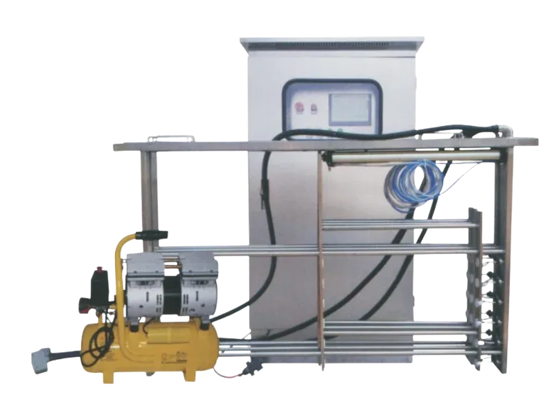
YONGFAN open-type ultraviolet sterilizer
Direct Application Engineering Support
Valve authority calculations, actuator torque sizing & wiring diagrams.