
YONGFAN HVAC - Premium Header
Engineered HVAC & Industrial Air Systems
YONGFAN HVACYOFAN HVAC Home
Fan Selection Guide | HVAC & Industrial Fans | YONGFAN
Aerodynamic Sizing & Fan Curve Matching

Fan Selection Guide: Airflow, Pressure & Duty Routing

Fan selection starts with one operating point: the airflow the system must deliver and the pressure or thrust required to deliver it under actual installation conditions.

Learn how to evaluate static vs. total pressure, account for ISO/TR 16219 system effects, select between axial (DTF/T35), mixed-flow (SWF/CDZ), centrifugal (4-72/SJG), roof (DWT), and tunnel jet fans (SDS) for commercial and industrial ventilation.

Airflow Range 380 to 144,260 m³/h
Pressure Head Up to 3,200 Pa (4-72 Series)
Tunnel Thrust 191 to 3,046 N (SDS/SDS-R)
Standards ISO 5801:2017 · ISO/TR 16219
Industrial ventilation fan impeller and aerodynamic casing testing
Operating Point Engineering ISO 5801 Tested Performance Curves, Static vs. Total Pressure & System Effects
01 / Engineering Methodology

Do Not Start with Fan Diameter or Motor Power

A “20,000 m³/h fan” is incomplete without pressure. Two systems moving identical airflow may need a low-pressure tube-axial fan, a high-pressure centrifugal blower, or a tunnel jet fan.
Centrifugal and axial ventilation fans in industrial plant mechanical room
Testing & Compliance

ISO 5801 & ISO/TR 16219

Per ISO 5801:2017/2025 and ISO/TR 16219:2024 (System Effects), fans must be selected where the calculated system resistance curve intersects a stable, high-efficiency portion of the fan curve.

Static vs. Total Pressure Confusion

Comparing an 800 Pa total pressure rating with an 800 Pa static pressure requirement creates serious airflow shortfall because velocity pressure is omitted.

Impact: Under-delivery of design airflow

Operating at Extreme Ends of the Curve

Selecting a fan at the far right of its curve leaves zero pressure margin, while heavy throttling on an oversized fan wastes energy and causes acoustic stall.

Impact: Severe noise, surge & excessive power draw

Neglecting Inlet & Outlet System Effects

Sharp elbows immediately at the fan inlet distort the velocity profile entering the impeller, reducing actual delivered airflow by 15–30% in-situ.

Impact: In-situ performance degradation

Motor Size Over-Reliance

Increasing motor kW without changing the impeller aerodynamics or rotational speed cannot overcome missing pressure on a high-resistance duct run.

Impact: Wasted electrical connected capacity

The Reliable Fan Selection Sequence

Follow an engineering workflow that matches the system duty before locking in model numbers or physical dimensions.

01 Airflow (m³/h) → Static / Total Pressure (Pa)
02 Handled Air Condition (Clean, Hot, Dusty, Ex)
03 Architecture (Axial, Mixed-Flow, Centrifugal, Roof)
04 Duty Point on Curve (75–87% Efficiency Zone)
02 / Fan Architectures

Choosing the Right Aerodynamic Architecture

Compare YONGFAN axial, mixed-flow, centrifugal, roof, and tunnel ventilation families by airflow envelope, pressure capability, and motor arrangement.
Architecture 01 · DTF / DTXF / T35-11 Straight-Through In-Line · Up to 114,829 m³/h

Axial Fans: High Airflow in Compact Straight-Through Form

Axial fans move air parallel to the shaft. They are the primary choice when ductwork is in-line, installation space is compact, and system resistance is moderate.

DTF Series: 1,886 to 114,829 m³/h, 115 to 2,266 Pa total pressure, Ø350–Ø1600 mm. Relevant configurations documented for 280°C / 30 min smoke exhaust.
DTXF Series: Low-noise variant delivering 6–12 dB(A) lower sound with compatible flange dimensions.
T35-11 / BT35-11: Bifurcated design keeping motor in an isolated tunnel outside hot, humid, or solvent air (552–58,343 m³/h, 32–420 Pa, up to 80°C).

DTF Capacity
1,886 – 114,829 m³/h · 115 – 2,266 Pa Total Pressure
DTXF Low Noise
2,472 – 114,829 m³/h · 6–12 dB(A) sound reduction
T35 Bifurcated
552 – 58,343 m³/h · Motor out of airstream (to 80°C)
Ex Classifications
BT35-11 / DTF Ex builds for GB 3836 Zone 1/2
Pressure Basis: DTF, DTXF, and T35-11 publish performance on a total pressure basis. Account for velocity pressure when matching static pressure calculations.

DTF axial tube fan installed in-line with flexible connectors
DTF High-Pressure Axial Tube Fan
Ideal When:
  • Airflow path is straight in-line with duct
  • High volume exhaust or supply is required
  • Motor needs isolation from solvent/hot air (T35)
  • Acoustic sensitivity requires DTXF
Architecture 02 · SWF / CDZ In-Line Body + Centrifugal Pressure · Up to 144,260 m³/h

Mixed-Flow Fans: In-Line Form with Extended Pressure Options

Mixed-flow fans combine the straight-through layout of an axial fan with higher pressure development derived from diagonal impeller flow. Ideal where axial fans run out of pressure margin.

SWF Series: 1,430 to 144,260 m³/h, 125 to 1,314 Pa total pressure. Available as SWF-I (single speed), SWF-II (dual speed), and SWF-III (higher pressure). Approximately 2–3 dB(A) quieter than comparable centrifugals.
CDZ Series: 2,176 to 33,158 m³/h, 97 to 701 Pa total pressure, with motor positioned outside the airstream for humid or lightly contaminated exhausts.

SWF Scope
1,430 – 144,260 m³/h · 125 – 1,314 Pa Total Pressure
CDZ Scope
2,176 – 33,158 m³/h · 97 – 701 Pa (Motor isolated)
Acoustic Advantage
Approx. 2–3 dB(A) lower noise vs. equivalent centrifugal
Speed Options
Single-speed · Dual-speed (SWF-II) · High-pressure (SWF-III)
Application Role: Select mixed-flow when high airflow + moderate/high pressure + straight in-line geometry are required simultaneously.
SWF industrial mixed flow fan in commercial building mechanical plant
SWF Mixed-Flow In-Line Duct Fan
Ideal When:
  • In-line duct layout cannot accommodate 90° bends
  • System resistance exceeds standard axial capability
  • Dual-speed normal/emergency smoke duty is needed
  • Moist/contaminated exhaust requires CDZ motor isolation
Architecture 03 · 4-72 / SJG High Static Resistance · Up to 3,200 Pa Total Pressure

Centrifugal Fans: Maximum Pressure for Long Ducts & Filters

Centrifugal fans enter the selection when system resistance rises significantly due to long duct runs, silencers, multi-stage filtration banks, scrubbers, or process equipment.

4-72 Series: 1,131 to 46,988 m³/h, 372 to 3,200 Pa total pressure. The highest pressure capability in YONGFAN’s standard ventilation portfolio, achieving 75–87% peak efficiency in central curve operating zones.
SJG Cabinet Series: 380 to 15,070 m³/h, 65 to 820 Pa static pressure. Compact cabinet form with motor isolated outside the airstream.

4-72 Pressure
372 – 3,200 Pa Total Pressure (1,131 – 46,988 m³/h)
SJG Cabinet
65 – 820 Pa Static Pressure (380 – 15,070 m³/h)
4-72 Efficiency
75% – 87% in central recommended operating band
Discharge Angles
0°, 45°, 90°, 135°, 180°, 225°, 270° orientation options
Discharge Orientation: Centrifugal fan selections must freeze casing discharge angle and rotation direction (CW vs CCW) to match physical duct routing.
4-72 heavy industrial centrifugal fan in chemical process plant
4-72 High-Pressure Centrifugal Fan
Ideal When:
  • Ductwork contains heavy filter banks or scrubbers
  • Long discharge stacks create high static resistance
  • Cabinet form with low breakout noise is needed (SJG)
  • Process ventilation demands robust scroll casing
Architecture 04 · DWT / SDS / BT35 Roof, Tunnel & Hazardous Duty Sizing

Roof, Tunnel Jet & Explosion-Proof Ventilation

Specialized applications require selecting equipment by physical interface, thrust physics, or hazardous gas classifications rather than conventional duct pressure.

DWT Roof Fans: 1,560–50,000 m³/h, 11–407 Pa static pressure. DWT-I (centrifugal) for higher pressure; DWT-II (axial) for high-volume low-resistance exhaust.
SDS / SDS(R) Tunnel Jet Fans: 7.9–71.8 m³/s, 191–3,046 N thrust, Ø630–1600 mm. Selected from thrust momentum Ne, not static pressure.
Explosion-Proof Series: BT35-11, DFBZ/BDFBZ, BWEX, and Ex DTF certified under GB 3836 for Zone 1/2 hazardous gases.

DWT Roof Scope
1,560 – 50,000 m³/h · 11 – 407 Pa Static Pressure
SDS Tunnel Thrust
191 – 3,046 N · 7.9 – 71.8 m³/s · 4 – 90 kW
Ex Protection
GB 3836 ExdbIIBT4 / ExdbIICT4 documented
Smoke Extraction
280°C / 30 min documented builds (DTF / PYHL-14A)
Fire vs. Ex Independence: High-temperature fire smoke duty (280°C/30min) and explosion-proof rating (Ex) solve different hazards and must be specified independently.
Industrial roof exhaust fans and weather caps on commercial building rooftop
DWT Roof-Mounted Industrial Exhaust Fan
Key Application Rules:
  • DWT requires roof curb coordination before waterproofing
  • SDS requires effective thrust Ne calculation
  • Ex fans require hazardous zone, gas group & temp class
  • Smoke fans require verified test certificate scope
03 / Selection Matrix

Ventilation Fan Family Routing Table

Match your system conditions directly to the primary YONGFAN fan architecture to investigate first.
System Condition First YONGFAN Family Published Operating Range Why Select This Family Action
High airflow, straight in-line duct, suitable pressure 1,886–114,829 m³/h · 115–2,266 Pa Total Pressure Compact tube-axial in-line architecture Configure DTF
In-line duty needs more pressure or dual speeds 1,430–144,260 m³/h · 125–1,314 Pa Total Pressure Mixed-flow pressure with straight in-line body Configure SWF
Humid / lightly contaminated in-line exhaust 2,176–33,158 m³/h · 97–701 Pa Total Pressure Motor isolated outside main handled airstream Configure CDZ
Higher-resistance duct, filter, or process system 1,131–46,988 m³/h · Up to 3,200 Pa Total Pressure Maximum pressure development & 75–87% efficiency Configure 4-72
Compact service-space cabinet exhaust 380–15,070 m³/h · 65–820 Pa Static Pressure Cabinet centrifugal, motor isolated outside airstream Configure SJG
Hot / dusty / solvent air at lower pressure 552–58,343 m³/h · 32–420 Pa · Up to 80°C Bifurcated motor-out-of-airstream bypass tunnel Configure T35
Direct rooftop exhaust ventilation 1,560–50,000 m³/h · 11–407 Pa Static Pressure Roof-mounted centrifugal (I) or axial (II) route Configure DWT
Longitudinal tunnel ventilation 7.9–71.8 m³/s · 191–3,046 N thrust Thrust-based aerodynamic longitudinal momentum Configure SDS
Car-park jet induction & smoke Sizes 2.5A–14A · 280°C / 30 min fire build Reduced-duct open-space induction sweeping Configure PYHL
Classified hazardous gas/vapor area GB 3836 Zone 1 & Zone 2 ExdbIIBT4 / IICT4 Configuration-specific explosion protection Configure Ex
04 / Procurement Protocol

Information Required for Fan Sizing & Selection

Submit these 14 engineering parameters to freeze fan duty points, select impellers, and verify electrical and acoustic margins.
STEP 01

Airflow & Pressure Basis

State design airflow (m³/h), required pressure (Pa), and whether pressure is specified as static (Ps) or total (Pt).

STEP 02

Handled Air Properties

Provide air temperature (°C), moisture, dust loading, solvent vapors, or classified flammable gas composition.

STEP 03

Physical Installation

State mounting orientation (horizontal/vertical/suspended), duct connection dimensions, and space access constraints.

STEP 04

Duty & Electrical Controls

Specify voltage/frequency, single vs dual speed, VFD suitability, noise criteria, and emergency smoke (280°C/30min) or Ex rating.

Engineering Handoff

14-Point Fan RFQ Checklist

Send your duct calculations or equipment schedule. YONGFAN application engineers will issue model-specific performance curves, acoustic data, and dimensional drawings.

1. Required Airflow (m³/h or m³/s)
2. Required Pressure (Pa) & Basis (Static vs Total)
3. Air Temperature (°C) & Contamination
4. Installation Orientation & Duct Dimensions
5. Power Supply (380V/50Hz, 3-Phase, etc.)
6. Sound Limit / Acoustic Criteria (dB(A))
7. Normal, Standby, or Emergency Smoke Duty
8. Single-Speed, Dual-Speed, or VFD Inverter
9. Hazardous Area Ex Class (Zone 1/2, IIB/IIC)
10. Smoke Rating (280°C / 30 min if applicable)
11. Motor Protection IP & Insulation Class
12. Centrifugal Discharge Angle (0°–270°)
13. Tunnel Thrust & Reversal Time (SDS/SDS-R)
14. Physical Footprint & Maintenance Clearances
05 / Manufacturing Verification

Fan Quality & Performance Pre-Delivery Verification

Dynamic balancing, full aerodynamic run-testing, motor current checks, and high-temperature fire testing.
Dynamic Balance

ISO G2.5 Impeller Balancing

Every impeller is dynamically balanced on digital balancing machines to prevent casing vibration, bearing wear, and structural fatigue.

Aerodynamic QA

ISO 5801 Performance Check

Full run-testing for airflow, static and total pressure, motor current draw, rotational speed, and blade tip mechanical clearances.

Tunnel Testing

Dedicated Thrust Rig QA

SDS and SDS(R) tunnel jet fans are tested on a dedicated thrust test rig to measure true static thrust in Newtons against electrical power input.

Acoustic Testing

Sound Power Verification

Octave-band sound measurement for bare fans and 1D/2D silencers to verify catalog acoustic attenuation and noise compliance.

06 / Engineering Knowledge

Fan Selection Frequently Asked Questions

Answers to key technical questions regarding static vs. total pressure, motor sizing, VFDs, and fan curves.

What are the two most important fan-selection values?

For a ducted fan: required airflow and required pressure at that airflow. For a tunnel jet fan: effective thrust (N) and longitudinal tunnel airflow.

Should I choose axial, mixed-flow, or centrifugal first?

Use system pressure and geometry: axial favors straight in-line ducts; mixed-flow adds pressure while retaining an in-line body; centrifugal handles high system resistance.

Can I choose a fan from airflow alone?

No. The same 20,000 m³/h airflow can require an axial fan, a mixed-flow fan, or a heavy-duty centrifugal blower depending on system resistance.

Should I use static pressure or total pressure?

Use the pressure basis defined by your duct calculation and maintain consistency. DTF/SWF publish total pressure; SJG/DWT publish static pressure.

Can I select a larger motor to solve insufficient pressure?

Not necessarily. Motor kW does not change the fan curve. The selected impeller diameter, blade pitch, and rotational speed must create the pressure.

Which YONGFAN fan has the highest published general pressure range?

Among general ventilation families, the 4-72 Centrifugal Fan reaches approximately 3,200 Pa total pressure with 75–87% efficiency.

Is a fire-rated fan automatically explosion-proof?

No. High-temperature fire duty (280°C/30min) and explosion protection (GB 3836 Zone 1/2) are completely separate certifications.

Can YONGFAN provide a performance curve before ordering?

Yes. YONGFAN issues model-specific performance curves, dimensional drawings, and electrical datasheets for engineer approval prior to production.

07 / Application Boundaries

Fan Selection Scope Ends at the Flange Interface

Understanding system boundaries ensures clear delineation of engineering responsibilities across HVAC projects.
Boundary 01 / Duct Design

Duct Resistance Calculation

YONGFAN matches fans to supplied operating points; calculation of duct friction, fitting loss, and coil resistance belongs to the MEP designer.

Boundary 02 / Acoustics

Room Sound Attenuation

YONGFAN publishes fan sound power levels; room sound reverberation, duct breakout, and room NC criteria modeling belong to acoustic consultants.

Boundary 03 / Electrical

Starters & VFD Inverters

YONGFAN provides inverter-duty motors where specified; external VFD drives, bypass contactors, and motor control centers (MCC) belong to electrical scope.

Boundary 04 / Civil & Isolation

Inertia Bases & Springs

YONGFAN supplies fan casing mounting feet; concrete inertia bases, spring vibration isolators, and structural floor loading belong to structural scope.

08 / Engineering Handoff

Request Professional Fan Selection

Send your required airflow, static or total pressure, handled air conditions, and installation constraints — YONGFAN application engineers will provide certified performance curves, dimensional submittals, and quotation packages.

Airflow (m³/h or m³/s) Static vs. Total Pressure (Pa) Axial, Mixed-Flow, Centrifugal, Roof 280°C / 30 min Smoke Exhaust GB 3836 Explosion-Proof SDS Tunnel Thrust (N)
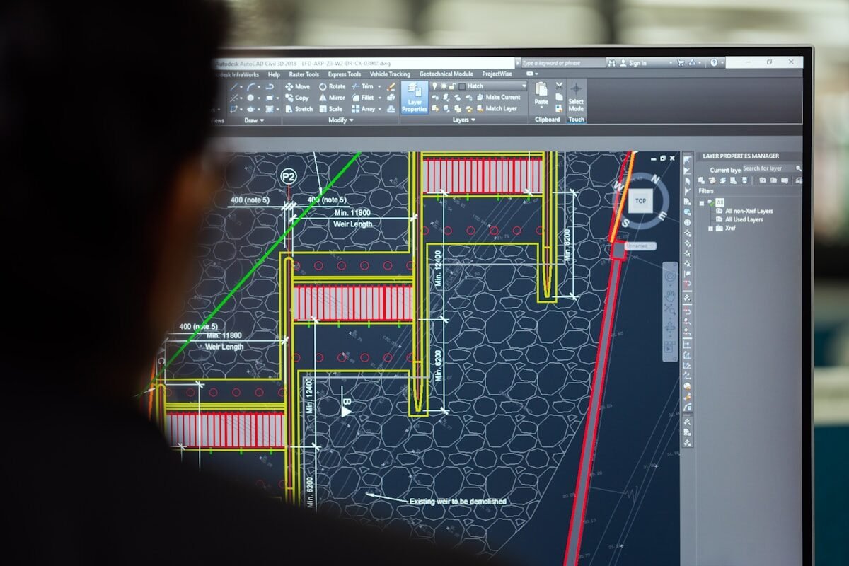
Engineers reviewing industrial fan curves and aerodynamic duct drawings
Ventilation Application Engineering
ISO 5801 tested curves, system effect mitigation & duty-matched motor sizing.